I came up with this idea experimenting with alternative ways to create a ring modulator using bridge rectifiers.
The result is a combination of octave up and ring modulator. Ive tried it on breadboard and pleased with the result:
Heres the schematic (the circuit simulator didnt have an optocoupler so I made a mockup one using an led and current controlled current source, the real circuit used a 4n35 but I dont think it would be difficult to accomodate other types)
Yes, it has a distinctive sound, I think the nonlinearity in the optocoupler adds to the distinctive sound. I will try to post a recording of it tomorrow. Can we upload audio files on this site or to I need to put it on youtube or similar?
The optocoupler transistor was wired as an emitter follower and I used a 56K resistor from emitter to ground, I think some sort of buffer might be needed at the output.
Apologies for the ambigious schematic. I did have access to LT spice but now our PC is in my daughters room. Now I do most things on my tablet.
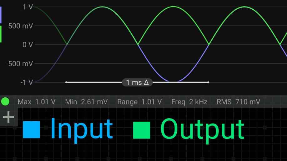
I replaced the optocoupler with an LED and found the current was < 700 µA, not enough to light it up much. So the lack of anything from the optocoupler isn’t surprising.
I changed the 8.2k resistor to 1k and now I do get a good output:
Interesting circuit. I think you need a different description, though. Since there’s nothing like four quadrant multiplication going on, “ring modulator” is probably not the term to use.
A short video demonstrating the sound of the effect. Input one is from a 3340 VCO, the second input is from my signal generator. Be kind this is my first ever youtube video!
Here, I find a good use for a David Haillant Euro Stripboard PCB v1.3 (from Synth Cube), a blank 4hp panel, and some spare parts. Great work, loverly sound!
(cross-posted on Youtube to pump “the algorithm”).
Playing some more with my simulation I find you can indeed get outputs resembling what you’d expect from a ring modulator, at least if you look at the LED current:
I’d guess there are other optocouplers that could produce voltages more similar to the LED currents. Not that there’s anything objectively bad about this distortion, you might like the effect.
This was using a higher frequency square wave and a lower frequency sine of the same amplitude. The resemblance to a ring modulator output might go away if using different waveforms, or if the square wave amplitude is smaller than the sine’s — here’s the LED current for the latter case:
In the case of my circuit 2 waveforms are added toghether then sent to the fullwave rectifier/V to I converter. Im not good enough at the math to say whether or not doing this yields the same result as a ringmodulator. The optocoupler functions to convert current output from the rectifier to voltage output but in a very non linear way!