If the rotary switch has more pins than your using it’s possible you’ve started on the second pin or have not set the limit on the switch. Open it up and ensure the limit washer is in the right place. I have lost count of the number of times I have forgotten to set up a guitar’s rotary lock and ended up with extra steps that go nowhere.
2 Likes
Yes, i did set the ring to have 8 turns (i think).
I cannot turn further to the right but maybe im counting wrong.
If the rotary is fully ccw, to the left, is it then 1 or zero?. So if i turn it 1 click, is that 1 or 2? That im not sure of.
This is what i want to achieve. I like to have Q1..Q8 corresponding with the front panel led’s as follows.


I quadrupletripleoctahexagon checked the CD4017 pins to goes to each transistor base. In that order as picture above.
Next the emitters from those transistors:
Q1 stays as is. Lets say this is step 1. Right? No rotary switch involved right? Emitter goes to potentiometer 1 with led 1 as in picture above.
Next emitter Q2 goes to potentiometer 2 with led 2 AND pin 1 of the rotary. Right? or….
At this point i dont know because i want everything vertically. Now it goes horizontally. Step 1, step 5. Step2, step6, step3, step7 (front panel picture led’s) etc.
Ofcourse i could change the labelling but when i turn rotary to 2, steps 1, 5, 2 and 6 are going huh???. So im in a total loss right now.
When i turn the rotary to 3 it jumps to another 6, 7 as if 2 transistors are triggered at the same time. So again brainfogged.
when i turn rotary to step 4, only led 1 stays on. Huh(???) Wtf?? Hahahaha. So yeah. I already resoldered everything, trying other order like 10 times and slowly my soldering points are getting fragile.
could somebody provide me with a drawing or something? Thanks
1 Like
It finally works now. For the most part. By trial and error. I removed all wires to the rotary and then tried each wire to see which led came up. And so on i tried and now it works BUT. After led 8 it makes a hidden step (ninth step i think) and then to led 1 first step. Why does each step nicely return to step 1 and step 8 not? I set the rotary washer to 8 so.
I works when connecting pin9 of the cd4017 to the center pin of the rotary. Then it goes directly to step 1 but that introduces another problem. When turning rotary to lets say step 6, steps 7 and 8 will be included but with very dimmed led’s. Thats not good either so i removed the connection. What else could be going on why after step 8, it makes an extra step before returning to step 1?
1 Like
My first thought is to isolate the 4017 and ensure the trigger to reset is working correctly. I’d also tie any spare pins to ground. Beyond that I’m stumped.
Could you create a manual gate/clock signal to test the state of each step. I’ve heard about your extra step issue a few times and mostly it’s either unassigned pins adding time/steps or a faulty chip.
9 times out of 10 the fault will be in relation to the clock enable or reset pin.
1 Like
Hi Farabide,
thanks for joining in, uhm, if I use only 8 steps, from a CD4017 chip, I normally connect pin 9 to the reset pinn15. in this case the Haraldswerk schematic, pin 9 isn’t connected to anything. Thats what’s throwing me off a little bit because in my baby8 sequencer, I connected pin9 to reset and everything works straight away. I also had no problems wiring the Rotary, so im not sure why this project feels more difficult? what im missing? anyways, when I get home I will try to swap out the chip. I hope its a faulty one, if another chip does the same, im thinking what to do with pin 9. or should I leave pin 9 out of the equation?
1 Like
I certainly can try that. I will use my piezo gate trigger module from @analogoutput
1 Like
Hi I popped you some of my notes on analogue sequencers in the hope it’ll assist. Baby 8s were a grey area for me when I started (and still a bit if I’m honest). I got an AI to make sense of my sequencer notes and break out/down the sequence cycle.
Way too much AI waffle to safely post here but I’m hoping my puffed out notes will help.
All the best
Sandy
Ps. A firm rule for me with any ic is that if any pin is unused tie it to ground. 555s and other ‘counters’ are susceptible to noise/confusion. There are I believe a couple of exceptions to this practice but I cannot for the life of me remember what they are.
2 Likes
@Farabide One exception to tying pins to ground is if they’re an output - you really don’t want to short a high-level output to ground. Q9 of a 4017 is an output. Similarly with op-amps - if you have an unused op-amp in a package, tie the inverting and non-inverting inputs to ground but leave the output unconnected.
@Marty It makes no sense to tie pin 9 (this should have been Q9) to anything, it’s not involved in the sequencer circuit and as an output you don’t want to tie it to ground. If you connect any of the Q outputs to the centre pin of the rotary it will effectively cause a low impedance short-circuit to gound for the output you’ve selected as the ‘end of loop’. That’s probably why the LED is dim - the selected output can’t give a high enough voltage to turn the transistor on properly and it won’t be able to trigger the 4017 reset.
There seems to be some confusion about the Q outputs of the 4017 and the sequencer steps - they are:
Q0 - Step 1; Q1 - Step 2; Q2 - Step3; Q3 - Step 4; Q4 - Step 5; Q5 - Step 6; Q6 - Step 7; Q7 - Step 8
Q8 is only used to reset the sequence to Step 1 when the full 8 steps have been completed. It goes high, resets the 4017 and Q0 immediately goes high, so returning you to Step 1. At least that’s what should happen.
This is the corresponding bit of the circuit from my (fixed 8-step) sequencer:
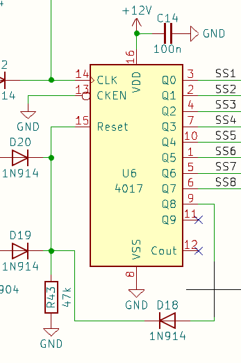
The only significant difference is that the Haraldswerke circuit has a rotary switch enabling you to select sequence lengths of 2 (Q2 connected to the reset pin) through to 8 (Q8 connected to the reset pin). Note that it’s the step after the desired sequence length which gets connected to the reset input of the 4017.
If all other sequence lengths work reliably I would firstly check again that you really have connected output Q8 (pin 9 of the 4017) to the ‘8-steps’ terminal on your rotary switch. If that is the case, check the value of R9 (the pulldown resistor connected to the reset pin on the 4017. In my sequencer (based loosely on a Fonitronik original) the equivalent resistor (R43) was originally 47k and the sequencer would very occasionally run a full 10 steps rather than the expected 8. Changing it to 100k fixed this issue. I can’t see why this would be a problem here but you could try increasing R9 to 150k or 200k. Failing that, try monitoring Q8 with your scope and check that you are getting a pulse on that pin when the sequencer moves from step 8 to whatever it does next.
2 Likes
Thank you all for the advice, i will read through your posts and see if i missed something.
1 Like
I will de- solder the wires from the rotary and start from Q7 and then backwards. Maybe this will solve the problem.
1 Like
This im gonna check, i think so but will check again.
Just to be sure, going backwards you need to start with Q8 and go down to Q2.
1 Like
Hi Clarionut.
I did and now it works!! Im happy.
Ok 2 things, Pin 9 should be connected (in an earlier post i read that pin 9 should not be connected). This throwed me off a bit as i wasnt sure what to do with pin9.
Anyways, it worked, i learning something from it so proud to be a member of this group. Thanks everyone. Up to the next module. The dso138mini oscilloscope. Im sure that i need to overcome some bumps here so text ya’ll later and for now, have a nice day, evening and goodnight.
2 Likes
Glad you got it sorted out!
There’s real scope for confusion with 4017 sequencers. You’ve got to deal with the sequence step numbers, which don’t match with the Q output numbers, which don’t match with the physical pin numbers of the 4017 package. It’s easy to lose track of what you’re dealing with. I got confused myself in an earlier post - I did say pin 9 should not be connected when what I meant was Q9 should not be connected. Mea culpa…
2 Likes
Someone needs to write a new, detailed paper on the use of the 4017 in sequencers. And let me be the first to commit here to ensuring it’s not going to be me!
I’ll stick with the proper fabled woo woo and the magic smoke offerings of hardcore synth DIY.
2 Likes
I will make a drawing how to wire things up, now when its fresh & clear in my mind, i might as well put it on paper.
1 Like