Makes sense  …
…
Thanks again to Christian for this board and panel!


(First use of one of my new boards, a little Euro/Kosmo power breakout)
6 Likes
Damn thats gorgeous.
4 Likes

That is important. Looks great!
2 Likes
nice , love the colors / layout .
i needs me one of these.
1 Like
@ChristianBloch, are your Gerbers available? Or extra panels? (The PCB Gerbers are on the Haraldswerk site linked in the first message here.)
Earlier in this thread:
2 Likes
wiring the panel for dummys please.
specifically the pots and the rotary switch.
There’s a graphic here HaraldsWerk Modulation Sequencer DIY What questions do you have? On the rotary switch “common” is the center pin and “2…8” refers to the numbers on the panel, they are pins 1…7 on the switch. So center pin to left side of 8-pin Molex, then pins 1…7 to the remaining 7 Molex pins.
3 Likes
is common the middle on the rotary? and then start with 1 -7?
SPDT on/off switch and just connect to the middle and bottom pins?
is CW and CCW from the backside or the frontside?
See above for the rotary
Yes
The usual pot pin numbering:

5 Likes
lolol took me forever to realize you made an extra hole on your panel for mounting… lol
2 Likes
Hi, did you use this schematic?
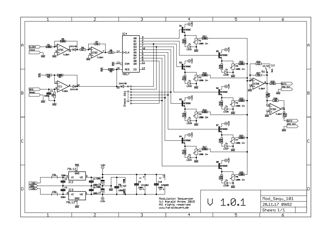
How did you wire up the 12 position switch? From the schematic, i really can’t tell what is what. Q1 is always on, Q2 is connected to RS1 socket or whatever it is. On the frontpanel i see steps that starts with 2 up to 8. Ok thats clear but Q8 connects to dot 7 of the RS1 connector. So following the pinout and/or transistor order it dont line up to the RS1 connector. Right? Or am i looking at this all wrong? Thanks in advance for your advice.
Hi Christian.
Ive build this module too and works fine except one little thing i cant get my head around.
The steps are working too but when it reaches step 8, next it should go to step 1. Well it does not. There is a ghost step (step9) and then it goes back to step 1. Funny thing is, when i dail the rotary back to 7, it steps to 7 like it should and after step 7 it goes back to 1 also good. When i turn the rotary to 8, it steps to 8 but after step 8, it does not go to step 1. There is a hidden step and after the hidden step it goes to 1. What did i do wrong?
I know this: the CD4017 is a 10 step counter. If i want to use only 8 steps, the next pin (pin 9) of the chip needs to be connected to the reset pin 15? So on the haraldswerk schematic, i do not clearly see where pin 9 is connected to. Besides the com pin (to diode), do i also need pin9 to be connected to the same point?
Thanks in advance for your help.
The 8 steps of the sequencer are outputs Q0 to Q7 on the 4017. So at the end of the 8-step sequence the ‘next’ pin, which should trigger the reset to step 0 (the first step), is pin Q8 - this is the ninth pin in the sequence. The Haraldswerke schematic has no connection to Q9 as that’s the tenth output and is not used at all given the maximum of 8 steps.
2 Likes
Hi, thanks for your answer. Yeah pin9 is not connected at all. Do i need to solder that to the center pin of the rotary switch?
No, Q9 isn’t involved in the circuit at all and shouldn’t be connected to anything. The common terminal of the switch connects to the reset (pin 15) of the 4017 via diode D3. Outputs Q2 to Q8 connect to the outer terminals on the rotary switch, to set the sequence length to 2 to 8 steps respectively.
If you study the schematic you’ll see that output Q8 only connects to the rotary switch in order to set the loop length to 8. It doesn’t have any of the circuitry to generate the control voltage outputs which are present on outputs Q0 to Q7.
1 Like
Ok, i can’t remember having issues when building the baby 8 step sequencer which has the same principle. On this schematic for some reason the points which goes to the rotary somehow throws me off a little bit. Need to check schematic again and map those Qxx to the rotary switch