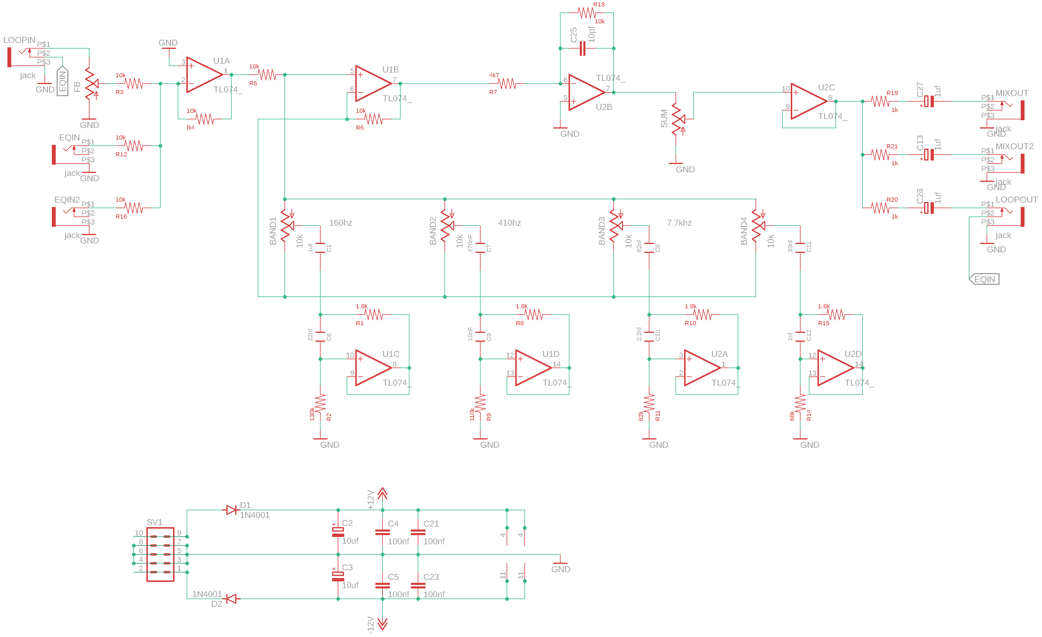
OK, I now understand (I think) that you’ve hard wired the output to the feedback pot. I thought you’d kept the LOOP IN input but instead you kept the EQ input. Makes more sense, I guess? In that case the value of the feedback pot could be 10k since it’s not on an input any more. But yes, if I were doing it I’d try 100k on the input jack and the feedback wiper (R3 and R12). However it looks like you’ve changed R5, not R4. R5 can stay 10k but R4 should match the input resistors, 100k. If built with the LOOP IN/OUT jacks then the feedback pot should be 100k. The sum pot can stay 10k or can be 100k, doesn’t matter (100k will draw less current but no big deal… 10k might be quieter? Not sure.)
At least that’s what I’d try, if I were building it, and when I say “try” I mean on a breadboard!
Wow, I forgot all about this thread! I can read a schematic a lot better than I was a few months ago…
I still want to give this one a go, I like harsh noises.
Where did you get the value for 100K on the feedback pot? I was looking through the BOMs on his site and couldn’t find any reference to it, but I think it should be a 10K like the others?
It’s a voltage divider, and it’s going into a 100k resistor, so 10k vs 100k shouldn’t make much difference — in principle it should respond less linearly with 100k but not very much so.
Not yet, all components are on my desk work, but for the moment it’s allways the time for me to play with sounds and cables
a bit like on a modular construction vacation, but still looking forward to going back and build some modules (and especially this one!!!)
 )
)