So you’re trying to build a filter supplied by 0 V and 20 V?
The SSO signal will be from 0 V to some fraction of 20 V. A TL07x will not work well with input voltages less than a few volts above its bottom rail. So you would have to add an offset voltage to the input, and maybe some attenuation, to put it in a range of say 5 V to 15 V, and then use a decoupling capacitor on the output to move it to ±5 V.
The issues are similar to what happens in a guitar pedal where the power is 0 and +9 V. Basically a voltage divider gives you a +4.5 V level and the input signal is shifted to center around that. The +4.5 level becomes “ground” in a sense. Take a look at some pedal designs for examples. See for instance here:
U1 also needs to operate with signals going down to 0 V and is essentially DC so can’t be capacitively coupled after the op amp. You could instead use a rail to rail op amp like an MCP6002 there. But for the audio section I don’t know if a rail to rail op amp would be usable.
It might be wise to look for a filter that uses only a positive Voltage for power instead of one that uses a split supply. There are several here. Furthermore you might want to have a look at the repository page.
I also think you would be better off with a circuit designed for single supply.
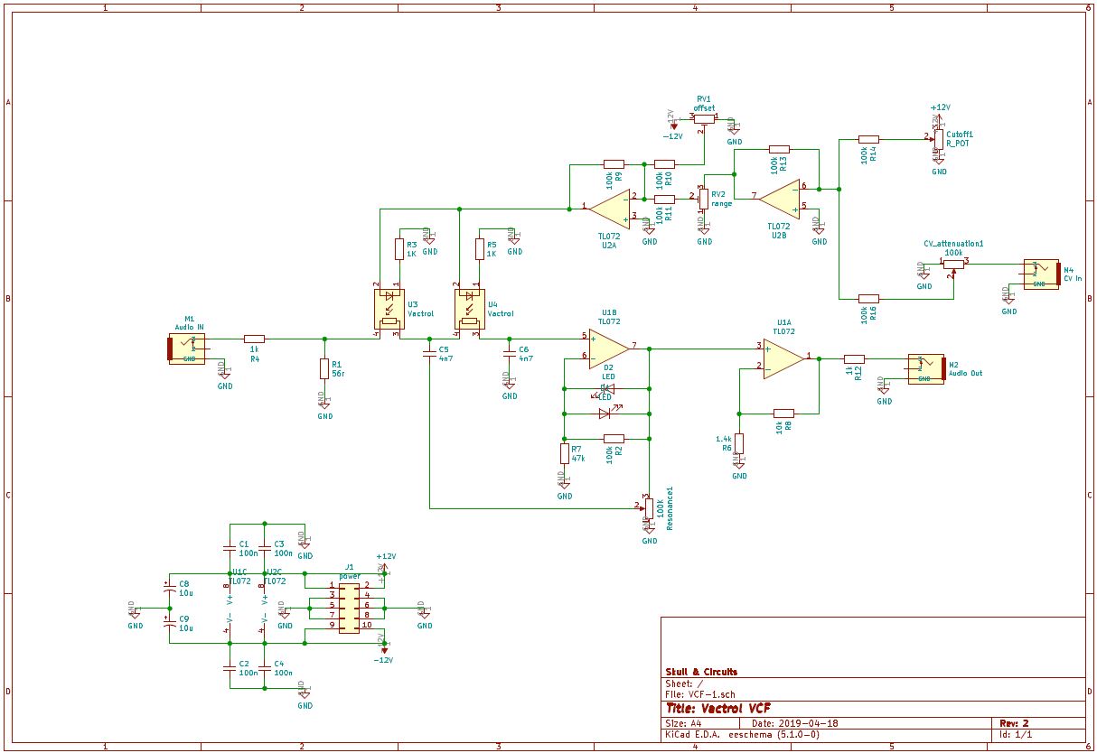
You could probably adapt this circuit but you would have to add voltage dividers and coupling capacitors. If you don’t add the capacitors, there will be dc offset on the output, which might not be desirable.
Designed for 5V, you could regulate your 20 V down to 5 and give your input whatever attenuation it needs. It uses a pair of CA3080s, you could probably substitute a single LM13700. See the discussion for other designs too.