 of course it is…you’re right. I wasn’t thinking about there being two on the build.
2 Likes
Quick question…Do I need to use thermal paste between the heatsink and voltage regulator? Also, I have a higher end paste that I used when I built my tower. I assume I can just use that, if it’s needed?
People can feel free to correct me, but I’ve been told it’s good, but not nessisary for this. If you got it, might be good though.
2 Likes
I figured it out now! The boards were working on their own, but the problem was that when I connected the two together, I mixed up the cables! I thought with AC it is impossible to do a reverse polarity error, but this is only true if you have only a single board  So I did not connect the two ground planes of my boards together, but connected the ground of one to the .
I am still wondering a little why I did not get a short immediately, but could measure the correct voltages of +12 and -12V on the outputs. Only when I plugged something in, it all went dark…
Anyway, thank you for your help and now I can add a lot more modules!! 
3 Likes
In single wart supplies, one of the 12 V AC lines is used as the 0 V rail, with the diodes/regulators producing +12 V and −12V DC relative to that (remember that voltages are always relative). If you mix up the AC connections, you’ll end up with two “0 V” rails connected to different AC lines. Which is fine, until you connect them to each other.
(Antoine mentioned this here)
5 Likes
Oh right! Point 2! Now I understand it! Thank you!
I really enjoy this community! Learning so much!
4 Likes
Okay, dumb question, I think. Should ALL of the LED’s go on when this is powered up and no modules are plugged into it ? Or, will only one LED light go on or two or ? (I do have the 5v parts connected too) I am just trying to see if I have put this thing together correctly. I am registering +12v on all of the bus connectors but only one of the LED’s stays lit up when it is plugged into the power supply.
All LEDs are supposed to go on as soon as you connect it to power. So you measure +12V on all of the connector pins?? that sounds weird, because most of them are ground.

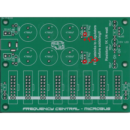
Can you check the voltage at the bottom pins of the regulators? The upper regulator should be +12V and the lower -12V.
edit: I marked it in this picture here:
4 Likes
So 2 of the LED’s come on (I had put them in backwards.) However, the 5V LED is not coming on. When I tried to measure the voltage at the base of the regulators it had a small spark and so I didn’t try again. 
2 Likes
Okai, 2 LEDs means that you have + and - 12V 
Can you measure the pins of one of the connectors and compare with the eurorack diagram? Be careful not to shorten the legs, that is probably where the spark cane from
3 Likes
So I am showing on my multimeter that I have 5V on the pins that say they should be 5V on the diagram. I am getting +12V on the correct pins as well. So where do you think is the issue between the pins and the 5V LED not coming on?
Should I try reflowing everything around the 5V LED? To be honest, I don’t know why I even need to have the 5V. I know Sam said he didn’t need it but I figured if it was there then I should put the components in.
2 Likes
Great! When you have 5V at the connectors, the only components that could be wrong are the 5V LED itself and the resistor next to it. You could check if you have any voltage between the legs of the LED and/or check its polarity… But as you said: Nothing uses 5V from the power supply, the modules that use 5V usually have their own regulators on board. I never bothered to put in the parts
4 Likes
I’m having a similar issue, I have low voltage on all the pins:
+12v reads as 2.9v
5v reads as1.5v
-12v reads as -8.5v
Not sure why but I thought I’d mention that the Walwart I got from eBay said it was meant for the Microbus but I noticed it’s output is 2000mA. But it’s still 12VAC out and reads as 15v (AC).
The +12v and -12v LEDs come on, the +12v is a little fainter than the -12v, the 5v does not light up but has flickered a few times.
Couldn’t see any obvious shorts and I checked a few of the sockets too.
3 Likes
Ok it looks like I put the transistors in the wrong spots, I didn’t pay attention and thought they were the same value. It was really hard to get them out too! I hope I didn’t wreck the board.
2 Likes
If you’re talking about the 7812 and 7912, they’re regulators, not transistors (there’s in the order of 20 transistors in each of them), and yes they have to be in the right spot as you’ve noticed  (the 78xx deals with positive voltages, the 79xx with negative).
When removing components, there’s usually a tradeoff: is the PCB more valuable to you than the components? If that’s the case, consider sacrificing the components – cut off the leads close to the PCB, and then clean up one hole at a time, using e.g. a toothpick to push pin & solder out.
6 Likes
Cheers! Yup that was the issue, now I’m getting the right voltages apart from -12v is giving -17v is this normal?
If you see −17 V on the output, odds are you’ve damaged the 7912 and it’s no longer regulating.
(you’d expect around 17 V on the input to the regulators, since that’s the peak voltage for rectified 12 V AC: the latter is given as an RMS value, so peak DC ≈ rms AC × 1.41).
3 Likes
Ah cheers, I’ll see if I can replace it
Replaced the 7912, but still seeing -17v on the -12v pin. Is there anything else I can look for? Having swapped the two regulators do you think I could have messed up some traces? I can see the traces on the back of the board, they seem to be working, but one of the legs, I’m not sure where it goes, is there a pin I can check against?
Also want to double check that a 2000mA power supply is ok for this project?