Guide to solder different jack sockets:
https://sudomod.com/forum/viewtopic.php?t=701
Very nice documentation for projects I checked, thanks!
Simple 40106 oscillator with diode‑based CV input - http://electro-music.com/forum/phpbb-files/rmr_001__simple_40106_oscillator_with_diode_based_cv_input_905.pdf
4 oscillator using single chip. You can make 6 of them if you do not want CVs, but this configuration seems to be more interesting for me.
I don’t think that’s related; that circuit just leaves 2 of them unused. The oscillators themselves are the usual schmitt-trigger circuits:

(as a side note, I wish people would drop that silly “astable multivibrator” name, just call it oscillator since that’s what it is. Or if you insist on honouring the French inventors by using their silly “oh look at the harmonics, it must vibrate in so many ways!” name, at least spell it multivibrateur ![]() ).
).
in comparison with the Super Simple Osc, it is the simplest in the world that people who toil with the other should rather do this one first (easy and less reasons that it does not work),
I did some things with this ship, notably a VCO / LFO bank module, on the other hand I made vactrol for the CV, someone has already tested this CV IN with only a diode?
I`m not sure if I understood - you suggest that there is possible to make 6 oscillators with CV in using this chip?
I based on this design, when I wrote that you can make 6 oscillators using this IC.
The schematics in the PDF you linked to (page 3) has four copies of the standard oscillator, with a diode for CV. Each one looks like this:

(pretty sure R1, D2, and C3 are supposed to be connected, btw, otherwise that thing won’t oscillate; cf the standard schematics I posted earlier)
…and two of the six gates are unused, for no obvious reason (guess he ran out of PCB/front panel space, maybe?):

If you wire them the same way as the others, you have six oscillators.
I found2 interesting projects for small Arduino oscilloscope. I want to use it as an audio visualizer in separate panel more than actual tool. Question is, witch one do you recommend more looking on the input signal ranges and code? For the second project I have spare LM1458N, will it fit instead of LM358N?
http://radiopench.blog96.fc2.com/blog-entry-997.html
http://radiopench.blog96.fc2.com/blog-entry-996.html
https://blog-imgs-138-origin.fc2.com/r/a/d/radiopench/20200427_OLEDosilloscope_V200E.txt
Thanks for the links. I had this idea of making an oscilloscope with an arduino for the same goal as you seem to have but had not put any effort in researching the topic so far.
From what I see when looking at the links, all of them will do given the goal you have set, which is visualising audio and not so much doing precise measurements. If you have no experience using an oscilloscope then I’d say take the simplest and try whether that does what you want. If after a while you get more familiar with its workings and find it lacking in some way, then look for a better one or adapt it. Oscilloscopes and their use can be very complex for noobs and it makes the learning curve quite a bit steeper if you start with one that has all kinds of functions that you hardly ever use or don’t understand.
If you are only going to use it in a euro rack context only, then you could maybe keep the complexity of the input circuitry to the arduino low and choose for the 2nd example, i.e. the ‘simplest oscilloscope’ on the instructible page. This will measure AC on A1 from -0.55V to 0.55V, but you could easily change that using a voltage divider / attenuator to -10 to 10 Volts (or whatever the maximum range of your euro rack modules is). It will measure DC on A0 from 0 to 5 V and if you want to adapt that to euro rack 0 - 10 Volts that can be done with a simple resistor attenuator. Because AC and DC will need a different attenuation, if you want to do these changes to the attenuation, I would remove the link between C1 and R5 and make a separate input for AC via C1 and one for DC via R5 for the sake of simplifying the whole circuit. In the more elaborate circuit the opamps are meant to amplify small signals. For your use case there is no need for using an opamp at all in the input circuitry.
To add the oled display to the ‘simplest oscilloscope’, hook it up to A4 and A5 as in the ‘oscilloscope with display’ and use the software that goes with that.
The circuitry for the radiopench blog scope is really easy, see schematic. Depending on your knowledge of arduino programming and electronics, you could start with that and then maybe move on from there.
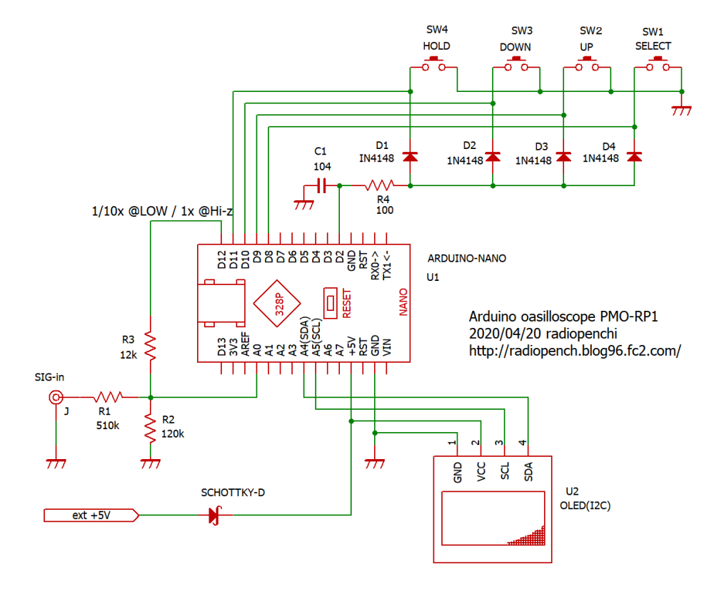
The source code for this project is very nicely documented, so that helps a lot when you want to change the scope or want to see how it works. The instructible page describes several variations of an oscilloscope as a whole in a more comprehensive way, so I’d certainly recommend studying that.
If you find it difficult to choose, build them all (sequentially) on a breadboard and try each of them out for a while, then make your choice and create a euro rack module from the chosen one.
Very interesting! A lot to absorb there; one thing I did notice from reading the comments on the “Matchbox” one is something that seems to suggest there may be issues with trying to use a Nano clone to do it. Might need a genuine Nano.
This repository doesn’t seem to be listed yet:
https://northcoastsynthesis.com/synth-diy-projects/
Smart guy with interesting articles in addition to well documented modules.
This really is a nice addition!
I guess if Barton is here then Nonlinear Circuits should be too. They sell PCBs and panels but the schematics are shown in the build guides.
Agree. As a minimum the schematic should be open so that people can build it in their own way. That’s why LMNC’s repository is allowed here as well, isn’t it?!
Some interesting stuff here but be advised this is a list of links that seems not to have been significantly updated since 2003 or earlier. Unsurprisingly, a lot of the links are dead (though you might find them on the Internet Archive).
Evan Kale… He recently took down a bunch of video’s and has just flat out dropped off the internet… but there are some good bits left over on his github github.com/evankale
I forgot this one 
http://experimentalistsanonymous.com/diy/index.php?dir=Schematics
Digisound 80 http://www.digisound80.co.uk/digisound/default.htm
Eddy Bergman https://www.eddybergman.com/