
4 Likes
Hello there! I’ve got the switches I was waiting for and the logic chips, so I have put a final circuit on breadboard.

The only thing in the schematic I left out was the momentary normally closed (on) memory clear push button switch. I used a dpdt switch for the memory clear/ mute switch. Works great! I’m just waiting for all the resistors I will need for the 4 in 1 panel. I ran out of 100k resistors and 47k.
2 Likes
I’m so glad!
Thanks for the feedback, I’m happy that the clear/mute switch also works as intended! Did you use a 1M resistor or something lower?
I used a 1M. Thanks again for the design. I’ve been putting off doing this module for a while. I have been putting a lot of thought into which module I was going to use to finish off my rack. I really didn’t have any reason to put it off any longer especially after your explanation of the schematics. Kristian is a little hard to follow sometimes. I’ve watched a lot of his videos. I’ve had small problems making some of his designs work so I wasn’t exactly in a hurry to build his design. I probably would have just tried one time and moved on if it failed. You know I had trouble even with your circuit (easy to fix but trouble nonetheless), and because I had faith in your design (which you stood by and in good faith) and encouragement from this forum I have a working breadboard of exactly what I’ve wanted to finish my modular rack. BIG THANKS TO ALL!!! ![]()
![]()
![]()
1 Like
That’s really nice, I hope you’ll have fun with your system!
1 Like
Surely 1 rack wont be enough!
3 Likes
I need to make a utility type rack. But more like a base to set the rack on. I will build a base with a 12 channel mixer with mute switches and a switch activated echo effect and distortion effect. It will also have a 40 step cv/gate sequencer (bigbaby 40 why stop at 32 when you still need 4 decade counters??..). Probably gonna need a couple 1 to 5 buffered multiples, as well. Definitely my next project.
2 Likes
Better make it a 16 step sequencer…![]() Switches and potentiometers are adding up on 40 steps with cv and gate…
Switches and potentiometers are adding up on 40 steps with cv and gate…![]()
So I finally finished my module with 4 circuits. Something weird happened though. For the last module I couldn’t get it to work. Specifically there was no output from the tap opamp (the opamp comparator for push button input). I rigged up a test led and the button worked made the led light up when I tested at the non inverting input but did not light up when I tested from the opamps output. Don’t ask me why or how I decided to try this solution, but after checking and rechecking until I was going a little crazy I SOMEHOW put a 1k resistor to ground in parallel to the 47k on the inverting input…and it works. I realize now that it is basically a 1k resistor going to ground and the 47k may as well not even be there. ![]()
![]()
Not sure I fully understand your tap input… Is there a reason the debouncing cap connects to +12 V rather than ground? And I don’t know what the 100k to ground is for, unless you wanted to reduce the input voltage by about 10%.
The threshold on your comparator (as shown in the schematic) is 12(47k/147k) ~ 3.8 V. Even after the 90% voltage divider and the debouncing the signal from the button ought to be way above that, so I’d expect it to work. But if it didn’t work until you put in the 1k resistor, which reduces the threshold to 12(1k/101k) ~ 0.12 V, then that suggests the button signal is much lower than it ought to be, if everything else is as the schematic shows.
I didn’t design it. I seriously can’t even remember how I got that solution. I was testing with an LED to see if the tap signal was getting to certain point in the circuit like at the inputs and the output and at some point I wanted to see what it would do at the inverting input when I pushed the button and it worked. One thing to another and I lose the led and just try the 1k resistor I was grounding the led with and it works the same. I hooked it up and put it in the rack. ![]()
Strange. As mentioned, the comparator is set up for ~3.8V so a 5V input can easily trigger the module, even after the diode voltage drop (the manual tap is way higher).
Could it be that the 47K was not connected properly to GND so that V- only receives its input from the +12V rail?
The tap button input part: that comes from Kristian’s schematic and I did not change that at all. Noise reduction maybe? I’m not an expert to be honest. That could also be improved, thanks for the remark!
1 Like
Incidentally… the op amp output should be either about +10 V or -10 V. Reverse biasing an LED at -10 V is not a good idea. Most LED datasheets show a maximum reverse bias rating of around -6 V. That doesn’t mean they WILL burn out at -6.001 V and obviously you didn’t fry yours but it isn’t guaranteed not to happen.
If you put a normal diode (like 1N4148) antiparallel to the LED — cathode to anode and vice versa — that will protect it against high reverse bias. Or you could do the same with a different color LED (or just use a 2-lead bicolor LED) and not only will each protect the other, they’ll light up one color for - and the other for +.
1 Like
I like that option, but I only used the led to figure out if the signal was coming through the opamp. I had a 1k to ground the led. I ditched the led and just soldered the 1k resistor to ground from the inverting input. The module seems to work just fine.
I probed and switched out diodes and pulled my hair out…![]()
![]() I definitely checked the 47k connection, and in fact I reflowed all the solderpoints a couple times. I’m still clueless, but the module works now. All 4 circuits. Great module. These things happen to me. Fairly well documented proof in this forum…
I definitely checked the 47k connection, and in fact I reflowed all the solderpoints a couple times. I’m still clueless, but the module works now. All 4 circuits. Great module. These things happen to me. Fairly well documented proof in this forum…
1 Like
Hi Bobby, im building this module as we speak. YuSynth’s random gates but i do have a question. Each led has a 1k resistor to ground. I get that but since only 1 led is turned on at a time, is it possible to use 1x 1k resistor for all 8 led’s instead of having each led connected to an resistor?
Hello Marty,
I think theoretically it’s possible, however, it is not recommended.
I assume there are overlaps in the switching that can lead to noise and glitches. But maybe it’s not that fast, considering the circuit uses 4006 and 4051 and we’re generating gates for music, not building supercomputers. I’m not an expert in electronics, but connecting all cathodes together, then go to GND via a resistor would create a common offset at the cathodes that can lead to misbehaving LEDs. Or maybe that’s something completely stupid. If someone with proper knowledge could demistify this, it would be nice!
Anyway, I think installing a single resistor for all LEDs is not that big of a fuss, so I personally woudln’t skip them. Also, if you need to debug the circuit it’s much easier if your LEDs are not connected together!
(We could summon @EddyBergman, he built the Yusynth random gates: Eddy Bergman.com: Synthesizer Build part-42: 8 RANDOM GATES by Yusynth.)
1 Like
Thanks for your reply. You might be right about the switching thing. If there might be some slow overlap, the led’s could get to much voltage and burn out. Moneywise its no problem ofcourse but i came up with this idea just to simplify things.
Hi, hope you can shed a light on this one. Maybe i learn something new from it.
I noticed that the gate out jacks are connected “after” the led’s
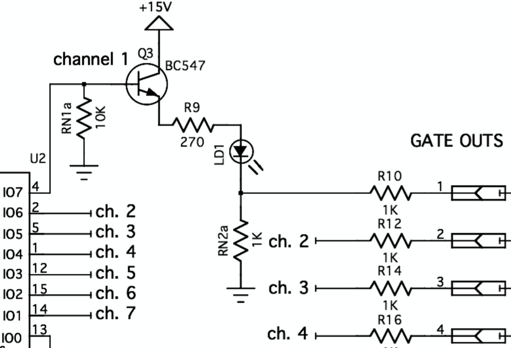
Since led’s only can handle 1.6v (i know that voltages differ depending on color), but does that mean that the output is also 1.6v? Should the gate output jacks not be connected directly to the emitters of the transistors? If the led gets broken, so will the output right?
I also know that you can connect an led to +12v but with a 1k resistor to ground. Or will +12v get passed through the Led? Will it be rectified somehow because a led is a diode?
Thanks in advance for your clarification
That 1.6V is the LED’s forward voltage drop. The voltage at the output jack will be (15V - [the base-emitter voltage drop of the transistor] - [the forward voltage of the LED]) * [the gain of the voltage divider formed by R9 and RN2a] = (15V - 0.6V - 1.6V) * (1kΩ / (270Ω + 1kΩ) ≈ 10V
2 Likes