Would it work to make the gain stage non-inverting? Then the input impedance wouldn’t be an issue, I think.
3 Likes
yeah ive got it, did the one burning out basically save the rest of my board?
i actually found the issue before i found the resistor
2 Likes
C4 is the filter cap from the +5V rail to ground. So yeah, shorting that wasn’t good.
Good idea before applying power to check for shorts from ±12V to ground and each other and, where there’s a voltage regulator, its output to ground as well.
Otherwise, well, a 10R resistor might fail and save the rest of the circuit, acting as a fuse, but that’s not what they’re designed for. An actual fuse would be safer. Or, again, check for shorts first.
2 Likes
Hmmm I’m not sure… tbh, I’ve not had much experience using non-inverting setups (I’m very new to designing my own circuits!)
I just went with an inverting setup since that’s what LMNC had one the final gain stage.
@lookmumnocomputer any thoughts?
1 Like
If you short a component it typically can not burn as there is not current flowing through it anymore. So C4 is probably oke.
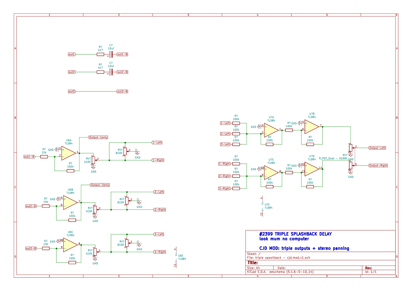
If the RV? A potentiometer is in the high position, so the output is at full voltage, and the RV? B potentiometer is either turned fully to x-Left or x-Right, this will short the output of the U6 op-amp.
That is probably not what you want.
Leaving out the RV? A potentiometers and connecting the op-amp output to to both sides of the RV? B potentiometer will work correctly.
If you wouldn’t be using inverting op-amps, you could simplify the circuit considerably. Then all you need is 3 potentiometers to pan the input signal to 2 op-amps that add the signals together (one for Left, one for Right). This would get rid of U6A, U6B, U6C, U7B and U7D.
1 Like
Won’t that still short the op amp output if the potentiometer is at max or min?
As it is or as you describe it I don’t see that the second pot does anything useful; the LEFT and RIGHT points are still connected to the wiper of the first pot (or to the output of the op amp). Shouldn’t the second pot wiper be what connects to the op amp output?
1 Like
Yes, you’re right, there should at least be a series resistor connected between the output and the potentiometer.
Yep, both ends of the RV? B potentiometer in the circuit as it is now always have the same voltage. So the whole approach makes no sense unless you rotate the potentiometer 180 degrees and connect the wiper to the output of the op-amp AND leave out the connection between x-Left and x-Right. You can even leave the RV? A potentiometer in the circuit and connect the wipers together if you want an overall volume control.
But not using inverting op-amps here will simplify the circuit considerably.
2 Likes
So something like this should do the trick.

If you use 100k Ohm pots and 100k resistors for the + inputs of the op-amps the impedance for all inputs will be high enough not to load the preceding circuit too much.
2 Likes
amazing, thanks!
But, without the with A pots, what could I do to control the mix of the 3 outputs?
1 Like
Yeah, that just does panning, it doesn’t give you control over the amplitude of each.
You’d need an attenuator, a pot wired as a voltage divider, ahead of each panning pot. I’m not sure what the input impedance of Jos’s panning circuit is, is it just the op amp impedance? If so you could use more 100k pots to attenuate the inputs. If not, if it’s in the 100k range, you’d probably need voltage followers between the attenuators and the panning pots.
1 Like
Okay, talking a very different approach. I realised that a big part of why I want pan controls is to use CV modulation to give me some nice movement (hook up 3x LFOs etc), so I switched to a voltage controlled panning circuit via dual VCAs.
Also added back in the Dry signal with its own pan controls, so in combo with @nervous_squirrel 's Wet Only mod everything can be nice a spatialise separately.
Any thoughts?

1 Like
Use a potentiometer of e.g. 100k Ohm per input to attenuate the input voltage. I didn’t add this to the drawing as I thought that would be obvious. So here is a new version:

1 Like
The op-amps have almost infinite input impedance, so any input impedance is determined by the sum of the pots and resistors. This is a bit too complicated to judge by eye, but it should be 10s of k Ohms worse case. Anyway if the output impedance of the signal sources is way lower, then this will not influence the signals in an unwanted way.
1 Like
Please do not see the following as me bashing you as a person or your post in particular. This post is meant for everyone posting schematics and strip board layouts etc.
When I saw the first version of this schematic I was confused because it said ‘look mum no computer’ in the description box and when I looked at it more closely I found the non working panning part and the bit that could lead to a short circuit. Only then I read the text in the posts more carefully and found that it was a draft modification.
Quite a few people visiting this forum are beginners in electronics. Judging from the many questions and comments about circuits that they do not manage to get working in one or more goes and diagrams they have difficulties reading, it is to be expected that they will not recognize these issues for what they are.
Therefore I think it is wise when you publish a schematic to make it very clear whether it is a DRAFT and / or UNTESTED or it is complete and tested.
Just add it to the text box and make this explicit.
Obviously this will not prevent typos from occurring. But that is something completely different from a published design that is not sound.
A schematic like the one you post here looks very professional so one might make the assumption that it will work ( people will not read the whole post to find out that it might be experimental in nature still ) and try to build it which will lead to unavoidable failure if the schematic is not correct.
There is a thread titled ‘Verified Strip board Layouts’, which exists solely because so many schematics and layouts are posted here and elsewhere that do not work because they contain mistakes and are not tested. As a result I mistrust any published strip board layout and either make my own or keep the schematic close by and check every part of the strip board layout against the schematic before I copy it.
So to prevent people from getting disappointed, wasting money on components or giving up on electronics as a whole I think it is good practice to add DRAFT to the description of the schematic as long as it isn’t a final tested version (and TESTED VERSION otherwise).
Maybe someone can add a ‘BEST PRACTICE’ paragraph to the page that welcomes new comers and add this as a recommendation?
4 Likes
Fair enough! Totally understand, and you’re right, I should have labeled those schematics as drafts and untested. Thanks for bringing that to my attention
2 Likes
The output section of the 2399 triple splashback delay schematic you publish contains a few odd things. The inputs to the op-amp are all connected together without any series resistors. So 1_Left is connected to 2_Left and 3_Left and 4_Left. So basically they are all shorted together. So what will happen if the op-amp producing 1_Left sets its output to +x Volts and e.g. 2_Left carries a different voltage? I’m not too familiar with OTAs, but I think this will not work.
It might be a good idea before publishing a schematic to simulate it and see whether it works.
Use e.g. http://falstad.com/circuit/. But there are many more online electronics simulators.
This allows you to draw a schematic AND test whether it works.
And as argued in other posts, please make a comment in the text box of the schematic that this is a draft and add your name. Now it looks like a ‘finalized’ publication by ‘look mum no computer’.
1 Like
No worries. I think it is wise to edit the posts and upload new versions of the schematics with added DRAFT label and your name as the co-author.
1 Like
Editied the ones I could, but for some reason it won’t let me edit the earlier posts
1 Like
Re series resistors, I thought that too, since that’s the norm for summing, but in the OTA circuits I was basing this on they weren’t used…