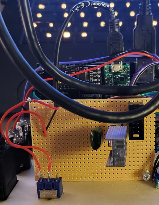
yes, your assumption is correct. they are not connected to each other (trough jacks), only by the power supply. i’d describe it as undesired cross talk. there is certainly room for improvement on my euro-5v-usb conversion.
1 Like
From my experience with the Gameboy and arduinos, you can already see improvement just by adding the two 10uF caps to the power connector ![]()
3 Likes
So I tried this filter and when I changed the cutoff frequency it sounded like it was causing my oscilator to sweep through octaves, is this normal???
There are conditions and settings that do mimic this. When the overdrive is in and the switch is activated crazy things can happen. A feature.
1 Like
Fair enough, I just built it and plugged it in with no idea what to expect so I was worried Id broken it.
2 Likes
There’s a youtube vid review floating out there that goes through all the “features”
2 Likes
Hey! I have a problem with the cutoff cv in. When nothing is connected to the cutoff cv (upper one, the one which is to be attenuverted) the cutoff is always open, the led is bright red.
When I connect 0V to this in, all works as expected (have not tried the other cutoff cv in). If I connect a LFO the the cutoff CV, I can see how it turns the Led red and green, but turning the attenuverter knob has no effect at all. Also the trimmer has no noticeable effect. Any ideas? I reflowed almost everything already. My guess is still that some of the components of the attenuverter are not well connected or bad, but it is difficult to find them on the pcb because the components are on top of the labels.
1 Like
try eric, he may have a scan
1 Like


Hi, maybe looking into Q1 and Q3. Just checking they are not 2n3904.
Is the sound of the filter ok ? If it is, then it is probably “just” a DC issue and you should find it by systematically going through the connections. There is a lot of +12V and -12V involved in this part, double check they are applied and the R values are correct… Good luck !
2 Likes
Yes, the sound is fine, it feels more like a floating input if nothing is connected. And the attenuverter does nothing… so maybe a missing ground there? I rechecked all of the joints, but I will also check voltages as you suggested ![]()
2 Likes
I’m dealing with the Chinese junk lm13700 issue right now. Amazon bridgold special… I just ordered some national semiconductor from jameco. Fingers crossed…
So… are the JameCo good?
In the past they were.
1 Like
I have built three modules. So far so good. The logo looks more like the one in rich’s pic than the china chips. ![]()
![]()
![]()
2 Likes
Am I correct in assuming FB1 and FB2 are ferrite beads? or are they 10r resistors?
Either will work. Shottky diodes also work to provide reverse voltage protection.
1 Like
FB1 & FB2 were in the early modules Ferrite Beads, in later modules they are indeed 10ohm Resistors and act essentialy as protection/fuses for short circuits. If you have a dead short they glow nicely and smoke a bit.
The Ferrite beads were discussed a few years ago and nobody had a solid reason for including them as their purpose was not clear ( at the time at least ). I think they are somethign someone in the mist of time added to a design and more people followed.
1 Like
See discussion here:
1 Like
Sup guys, a bit late to the parT (party). ive read a decent portion of the thread. Please I hope this doesn’t read overbearing or cross but here it goes anyhow, does this filter have two VCA cv inputs? it does huh?