I’ve found that one long vertical bar a few millimeters thick on the back of the panel over the part that falls between the rails will stiffen the panel up very well.
For this purpose I’ve often used 2 bars and in between stuck a PCB with some hotglue perpendicular to the panel which saved me from drilling (or printing) mounting holes for the PCB.
4 Likes
Not much direct progress on the rig lately. Went through a major office overhaul and ended up with a standing desk. My workspace is much improved in almost every respect. I’m still trying to get lighting figured out though.
I found out that the giant roll of solder that I have been burning through all this time had lead in it, so I pitched it along with the cutting mat I was using to protect my desk (I used swabs and they both tested positive). Thankfully I have been using an exhaust fan for a while, so hopefully no/minimal harm done.
Started putting together the roundhouse module. That thing really does use one of everything.
3 Likes
Could you let us have details. I have a number of old touch projects that I was planning to pass to a primary school and I’d like to make sure I’m not poisoning the wee lambs.
1 Like
Happy to oblige.
In 2020 when I fell down this rabbit hole (my god its been four years) I inherited this solder station.
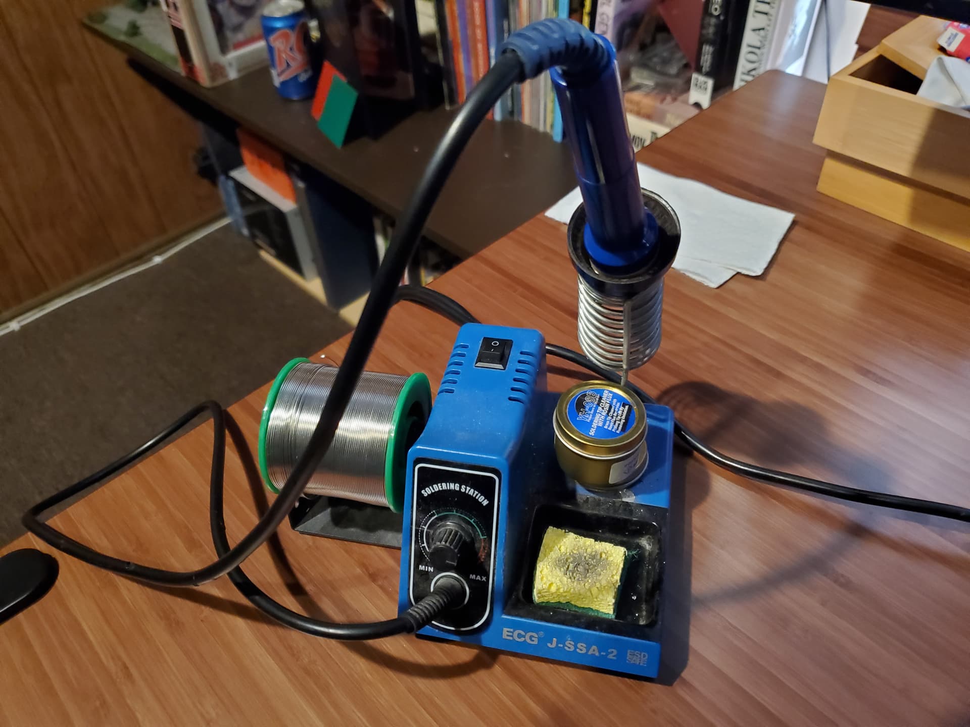
It came with a full spool of solder that I have almost completely used up. I didn’t really think much about it at the time and picked up a the box fan about a year later to help control the fumes in my office. And yes it really did take me this long to think to myself “You know, I eat at my desk sometimes and I should probably be a bit more concerned about my health”. I ordered some test swabs from bezos. They were less than 10$ USD.

I learned about the swabs from watching too many restoration youtube videos and thought it might not be a terrible idea to pick some up.

They are really easy to use - just get them wet with water and then rub against the suspected surface for 30 seconds, then compare it to the chart on the bottle. Gold = no lead, purple = lead. Chemistry is cool. I tested the spool directly and it turned dark purple. The green cutting mat that I have been using to protect my desk also came up as purple (though only faintly) so I chucked it in the bin and got a new one. I threw out the sponge on the solder station and got another tip cleaner for it as well.
I went around the office and swabbed all of my tools as well as the knobs on my synth since I figured they were the things that I use most and would be most likely contaminated. As far as I can tell none of them are a problem.
Now to be fair to my dumb self, all this time I have been washing my hands pretty religiously (thanks pandemic!) after each time I do any soldering. Hopefully that mitigated things a bit as well.
Live and learn. I hope this helps!
4 Likes
Fantastic, many thanks!
1 Like
Finished up the Roundhouse! Much thumpy goodness, but I severely underestimated the amount of noise I would get from my other modules. Just going to have to organize things differently.
1 Like
Could this not be considered chemical waste?
2 Likes
Only if the bin goes out. Usually our own bin is one of the first places we makers should look for material and parts. That way when challenged with, “that synth/guitar is rubbish!” We can smile and say “yes it is isn’t it, thanks!”
2 Likes
My understanding [citation needed] is that occasional lead exposure due e.g. to hobby soldering is nothing to be concerned about; what is concerning is chronic lead intake due e.g. to waste electronics leaching into water sources.
3 Likes
That is also what I have understood, but in no way I’m very knowlegable in these matters.
I’ve read that Beethoven according to one theory turned deaf (and ultimately died) because of lead poisoning, and that in his time people used plates and cups made from lead.
I put the leftover spool of solder into my e-waste bucket. I should put the cutting mat in there as well for when I take my next load of stuff over to them. They would likely have a better idea as to what to do with it than I would.
1 Like
I’m just trying to use the limited knowledge I’ve accrued over my life to try to do the best I can - which is all any of us can do really.
1 Like
A little acid, like vinegar, would be enough to scrub out /away most traces of lead. Then dispose of the water/wipes. Might save you binning anything useful.
2 Likes
I have been making little bits of progress here and there and both cases are getting pretty full. Case #3 looms large on the horizon. Perhaps next year. Sadly by the time I get around to it I will have likely been ousted from my garage workshop.
In the meantime I am troubleshooting and building backlogged modules. This brings me to some problems that I have been having that I could use some help with.
I have had moderate success in converting things from eurorack to Kosmo. My first SMD DIY project was a MI Branches. I would recommend it for any first timer. There were few SMD components and most of the ones it did have were on the larger side (large being relative in SMD terms). It works beautifully.
Skipping ahead, I purchased a second hand Calsynth Typhoon to “upsize” into Kosmo format. This was a much more ambitious due to the sheer number of components involved. I had mixed success. I did manage to pull off one trace - but rerouted it with some thin gauge wire. The problem now lies with (I think) with the normaling of the jack sockets. Plugging a signal into anything that the AUX input should control activates everything. Also sending a trigger to the hold/freeze function does not activate the hold, in spite of the push button working as it should. As a whole the module still “works” but it would be nice to have access to all of the features. I spent some time looking at the PCB layout - but there were no revelations for me there.
Later, I purchased a bare bones jakkplug uRings from pusherman. It was just the PCB with all of the surface mount and none of the pots, leds, or jack sockets. Perfect! Or so I thought. It works very well except that three of the five sockets are mostly unresponsive with one of those three acting strangely.
I am starting to think that the problems with both of these modules stem from a fundamental misunderstanding I have about jack sockets. All this time I have been using these - https://www.mouser.com/ProductDetail/568-NYS232
and I have always assumed that they were a 1-1 equivalent to the typical 3 pin eurorack socket. Perhaps this is not the case?
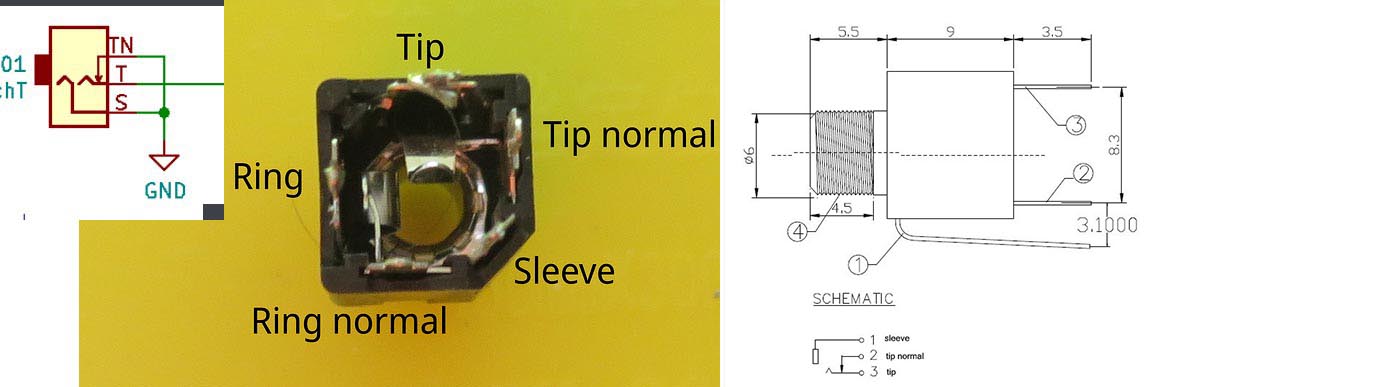
I have been poking over the schematic here:
nRings/schematic.pdf at master · jakplugg/nRings · GitHub and have not found anything helpful there either as well.
Ok, so with a little testing, it looks like I had some wires wrong on my Rings - its probably worth checking the typhoon as well.
2 Likes
I have not been able to do much with the synth lately - but I have been applying a lot of things that I have learned while building it to my job.
Currently I am diving deep into the ins and outs of DMX. There was an existing system installed and I need to understand how to make use of it - with no support from who designed it and put it in place.

Its slow going, reverse engineering everything. All of it was controlled by a raspberry / controllino that I had to rip out.
The system had to control light strips as well as the fixtures pictured. I think the D12 unit was running the fixtures, but I’m not sure what to do with the extra white wire I seem to have left over. The documentation on both devices is spotty as well.
2 Likes
Is the white not just bridging the D12 to the D4?
Nothing is connected in that picture yet!
1 Like
Yes, I saw that. I was suggesting the units and the RGB brick may need a common control line for dimming etc. one of my students works with this gear a lot, I’ve fired your photo to him for a ref or steer. I’ll get back to you when I hear back.
1 Like
I appreciate! I have made quite a bit of headway. One of the biggest helps was getting a DMX operator-384 and cutting into an XLR cable to start hooking things up. It is awfully nice that everything I am working with these days seems to run with +12v - which I feel somewhat comfortable with for some reason.
I found that the fixtures we have do indeed have an extra white channel that the smaller unit can control - but I think I will leave it out just to keep things simple. One of the bigger units seems adequate to control everything we need to control.
1 Like