The old resistor in question is not showing up as anything on my meter - but it might have been a 10m
10m would be 10 milliohms. 10 megohms would be 10M.
Yes! Sorry - pardon my caps or lack thereof. I suppose its only luck that I have not really noticed the difference up until this point.
I am now getting a chance to use my module tester and of course, nothing is ever as straight forward as I would like. When I have audio running to the audio in - the frequency does not seem to be updating as I would expect. It registers my tapping a cable with my fingertip but not when I plug in an audio source. I feel as if it was working when I first finished it a while back. Perhaps I inadvertently changed a setting.
Busy repopulating my case with modules when I noticed something odd. I have a routemaster powersupply and FC Power with a home brew bus in my upper case. I have everything plugged into the routemaster - but when I switch the filter over to the FC Power the filter no longer… filters. The signal just passes right through.
I know its not out of phase because I switched it on the FC P and things go very unhappy.
1 Like
My very first thought is that somehow in switching cases the jack sockets have bridged. Just a hunch.
Maybe a shared (or not shared) ground issue?
I dont think its the sockets - I left everything plugged in and switched PSU’s. I also have two routemasters in my lower case and everything works fine if I moved the module to them.
I’m thinking so. I might have to just bite the bullet and get another routemaster
1 Like
If you’ve got the capacity for making your own IDC cables you could make one that just conducts on the ground pins and connect the two busses together. If you can’t, let me know and I’ll ship you one, because 50¢ for a cable and a few bucks in postage is a way hecking better solution than dropping a couple hundo on a new power bus.
That is something I doubt I ever would have thought of. I can totally do that. Will try soon!
1 Like
Gave the grounding wire a go with no luck.
I pulled the PSU out to check it over and noticed that when I do continuity checks, the -12v indicator lights up - I dont think it is supposed to do that. Also the -12v rail is giving -15… perhaps a bad regulator?
So, that sounds to me like the indicator LED (or driver circuit) is drawing current from the meter, which is how the meter detects continuity–it sends current through the circuit and detects whether it makes it through. So, maybe it’s not an indicator of failure, but if you’re getting 15v out of a 12v regulator, it definitely sounds like a bad regulator.

Odd psu behavior still persists - but I swapped it out for a spare and the rest of the system works much better now. Swapping the regulator on the bad PSU didnt help. Looks like I’ll have to file it away on the troubleshooting pile for now.
I got the #1145 and #1158 in the case as well as the K25 glide. Upgraded my stripboard VCO module: new pots all around, fine tune knob, and a poly 1nf cap. Now I need to do the same on its twin. The blank space in the upper case is waiting for a wave shaper module that is next on the troubleshoot pile.
But first things first - I am still having the same strange drop out behavior of my square wave on the #1222 VCO. I thought I had it sorted but the signal still drops out after things warm up a bit. It still needs to be my main focus since the wave shaper that is going in next operates on square wave signals!
2 Likes

Oh, very brave!
The ancient synth lore clearly states;
“Dis the DIP and you’re in deep … [Lost in translation]”
That tl02 can bite my entire a**
Anyway, I fixed my square wave! Guess how!!
3 Likes
“Troubleshooting”, that’s how!
1 Like
Switched it up to a Fonzie double thumb? Heyy!
Its how today’s cool youngsters be waving i hear.
Percussive maintenance? Just give it a little thump!
1 Like
Overdue update!
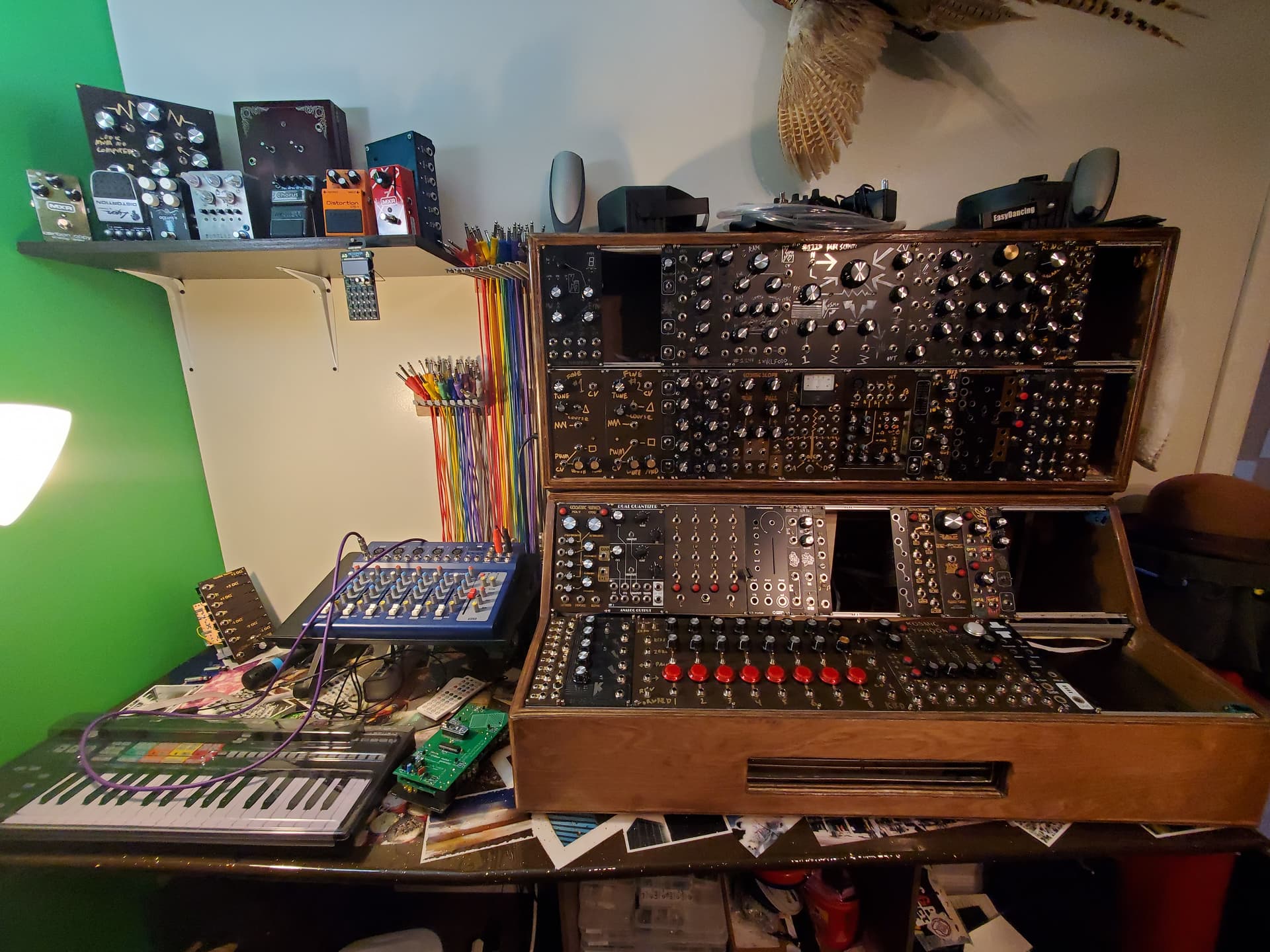
The good news: I have made great strides and my whole setup is further along than it ever has been. I cant say enough good things about the metal rails. The ability to slide modules and quickly swap them is fantastic and satisfying.
The bad news: My borked module pile is stacking up and I think I currently have more modules than I can fit into my cases. I suppose the second is a good problem to have.
I have gone through pretty much all of my built modules and cleaned them up. There was a lot of soldering flux left over on most them that I didnt bother/know I should clean off. I wonder how much effect it was having on things if any.
I did the fully wet mod on the 2399 delay. I like it a lot! My first time drilling through a pre made face plate was harrowing but went well. I think that my choice of different LED’s for different stages has a pretty profound impact on the tone that each delay puts out.
The fixed sine wave bank and the morse code modules are great sources for simple modulation and the slope generator worked on the first try. Also a silly thing that made me happy was my format jumbler:

I was asking a bit much from a 3d print with so many holes and it was sagging terribly. Some super glued in strips of aluminum seems to have stiffened it up and now it is rock solid.

Broken modules to work on:
Kinks - SMD issues. I really wish I could get this one going. It seems like a match made in heaven with the fixed sine wave bank.
Wave Shaper - 3 channels not working. I am assuming this is because I am bad at reading schematics and I dont understand how the barton PCB works.
Typhoon - Jack socket normaling issues. Flights of fancy are difficult to troubleshoot.
Big Mult - Same old LED and metering problems.
Safety Valve VCA - ???
Sequencer - Overall bad build quality since it was one of my first modules. The cheap pots are horrible.
2370 Spring Reverb - Aggressive hum even when not plugged into the tank.
Very pleased with progress over all.
10 Likes