Has anyone had any experience with the XL6007 boost DC/DC converter from XLSEMI (dataset)?
I am specifically interested in the little modules that you find all over AE for ~2$, in which XL6007 is configured as double SEPIC (fig 7 in the datasheet) which allows you to boost a lower input to +/-9, 12, 15…
In one of the more helpful videos, IMSAI Guy tested them with 5V at the input, boosting to +/-12 and you can certainly draw 50mA at -12V before it becomes unstable (while drawing more than that simultaneously at +12V).
I am interested in using them for a particular application where I need dual rail voltage from a single rail input, and I was wondering whether one can get better performance when using a similar, near, or even higher input than the dual rail output (e.g. 14, 15, or even 18V input for a +/-15V output).
In looks like some people have used them successfully in guitar pedals, but I haven’t found any “how to”, “what you should know before” kind of guides that would be useful in my intended use case.
XL7006 is only made by XLSEMI, a Chinese company, and the price of a similar IC at LCSC is only $0.28, so I am thinking that there might be less chance of the modules having fake ICs, compared to something that is advertised as having a Texas Instruments IC. Although one cannot exclude the possibility of the modules using factory rejects (i.e. converters with a much lower switching frequency).
I ordered one and will do some light testing to see what I am might be getting myself into.
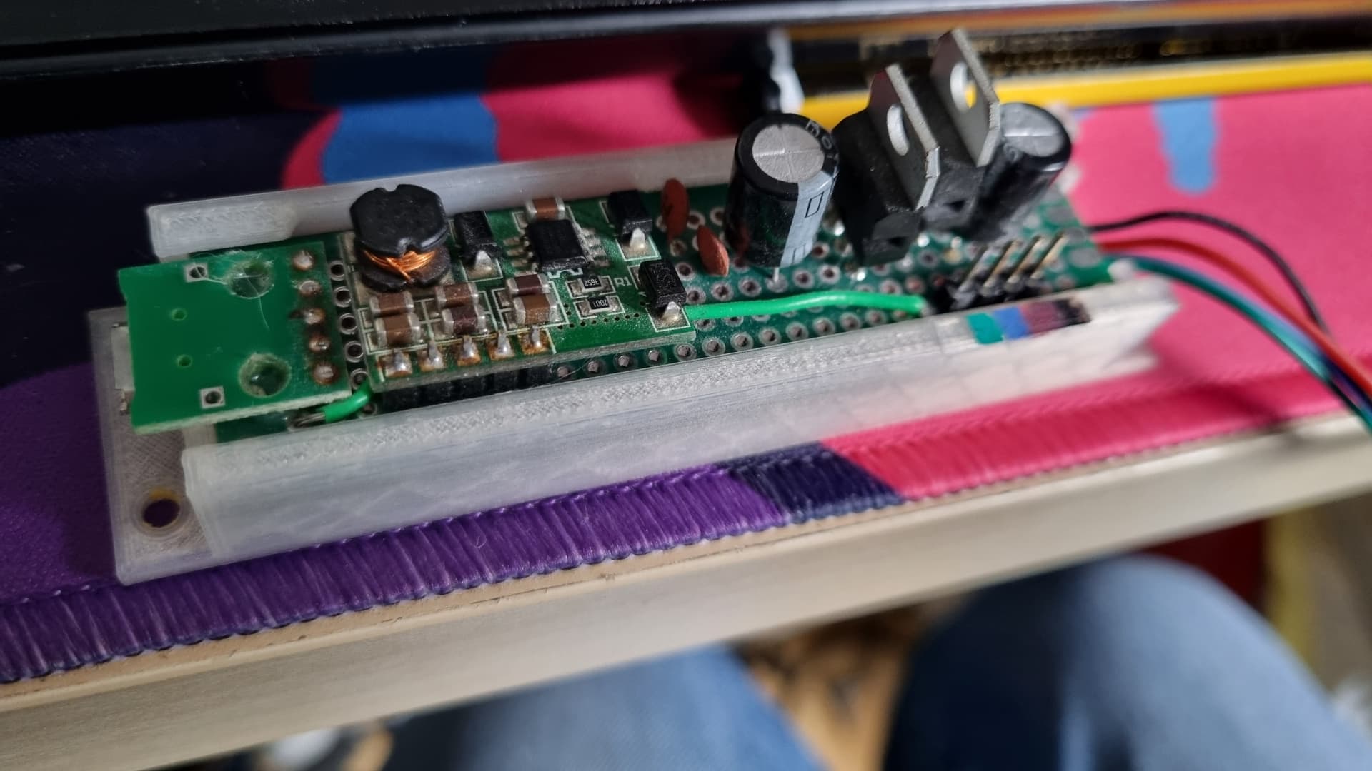
These boards have the same chip (although the chip is sometimes marked “Eletechsup DD1718PA”, the board designation):
I got a load of these off Eletechsup’s AliExpress store, where they’re less than a quarter of the price of Frequency Central’s stock. They have them for their Speak Truth To Power board which, looking at the PCB layout, is basically the “Low Noise ±12V” circuit that Eletechsup provide on that page.
It was the first thing I made when I started getting interested in DIY synths so it’s a bit janky, but it’s been really good for experimenting with things on the desk. One end has a micro USB connector for a battery pack, the other outputs a regulated ±12V. I can’t tell you the current it can handle, I’ve never measured it; Frequency Central reckon they can provide 600mA on +12V and 200mA on -12V, but Eletechsup say 120mA for -12V.
If I made it now, I’d use a USB C PD trigger, just to help things along electronically, but otherwise it does its job fine.
Thanks, this is very helpful! I had no idea that Frequency Central has been using them, so at least we get an idea that these might work.
I have a question though. FC provides 6-12V input to get the +/-15V, but I was wondering whether one could provide a higher input than the output. The difference sellers give conflicting information, and honestly I cannot put much fair in descriptions in AE. The XL6007 dataset example circuit in Fig. 7 says “Input 10V ~ 18V Output ±12V / 0.6A”, so it looks like this might be possible?
The XL6007 datasheet says “XL6007 operates from a 3.6V to 24V DC voltage.” Though a particular XL6007 circuit might have a more restricted input voltage range, as indicated in the datasheet example circuits. In particular, one of those circuits is labelled as a boost converter, which implies the input voltage must be lower than the output voltage.
I got my bench power supply to push 24V into my circuit, bypassing the USB port with hook-up wires. This wasn’t a good idea, as the circuit started making a squeaking buzzing noise… so I stopped that, looked at your question, dialled it back down to 18V and tried again. No buzzing this time. My outputs were fine, +11.9V and -12.1V. I couldn’t plug anything in to try and draw power from it because I had wires everywhere and was having to hold four things with two hands already. (The buzzing was probably due to this balancing act, seeing as there wasn’t any magic smoke.)
My circuit is ±15V with linear regulators to bring to ±12V, same as Frequency Central. I don’t imagine there would be any difference with the 12V version getting fed a voltage slightly above target. I wouldn’t have thought it the greatest idea though; as @analogoutput said, you’ve got a boost converter there. It may work, but it’s really not how it should work. You might find it becomes horribly inefficient and provides worse performance than an in-range value, or it might cause one of the passives to break, or shorten its life, or it might be perfectly fine.
My personal plan for a new version of this is to get the USB PD trigger to try and negotiate 12V, falling back to 9V then 5V (because the modules I have let me do that), and use a halfway decent charger to run it. I’m also going to put on power LEDs this time!
Many thanks for going into the trouble to do this!
I normally wouldn’t have bothered with such a converter as I have the regular AC/DC supply with linear regulators for my synth in progress and for the breadboard experiments, but I have a particular use case which requires a different approach.
I am working on a few valve/tube modules and I need 1) weird values (e.g. 6.3, 7, 8.5, 19V) supply for the filaments, and 2) either a bipolar +/-15 supply or a 24V (or more) supply for the rest of the circuit, depending on the module. To make more things complex, each module will draw anything between 100 and 450mA for the filaments, but typically <20mA for the rest of the circuit.
So far I have been powering the filaments with a 19V DC laptop “brick” (which has plenty of juice) regulated down with a LM317 when needed. For the rest of the circuit I just use my regular +/-12V supply. I was thinking that I could get that 19V (or perhaps a more sensible 18V) to a DC/DC converter per module to step it up to +/-12V, +24V or whatever is needed by each module.
In any case, I will post here my findings for anyone who might feel doing something odd like this.
Aha! Makes sense. There’s another Eletechsup module that you could use, DD1912PA, which is a bipolar buck-boost module. (I’m not sponsored by them, I’ve just found the modules I’ve had from them extremely good!)
This thread on diyAudio is very interesting as well - I hadn’t considered the unshielded nature of the inductors…
Part way down it moves to the DD1912PA I mentioned, and the last part of the thread suggests problems with driving SEPICs hard. A little power submodule for each module is probably achievable, and definitely worth a try!
Thanks! Very interesting! More reading, more testing ahead.
By the way, I have an analog voltmeter on my long to do list and I noticed that you have a nice looking one. Any chance that you’ve built yours on the design shared by Tim Stinchcombe?
Oh thanks! It’s nothing as fancy as that - the jacks are just wired in parallel and meter is the cheapest doesn’t-look-awful bipolar voltmeter from AliExpress. The switch powers a short length of 12V LED strip I had lying around which I’ve mounted across the top of the meter, pointing down.
Basically I had the same idea as Tim Stinchcombe - “I guess like many others, to me the idea of a large meter on a synthesizer seems pretty cool”. The other thing I knew I had to have is a rotary phone dial to do… something, somehow. So it pulses out on one jack, increases the voltage by 0.5v per pulse on the next jack and the last jack gets set to the end voltage when the button gets pressed (or sets it to 0v if you’ve not dialled). It’s there mainly for the aesthetic but is functional!
I finally got to test the couple of XL6007 double SEPIC modules I got a while ago from AE. One of them arrived slightly damaged (a bit of the top of the inductor was broken, got a partial refund, glued it back, it works) and the other arrived fine.
They were the +15/-15V variety, and with a typical switching 12V wall wart (12.4V with no load), I get +/-15.2V at the output with a small load.
When I put them in the circuit instead of the trusted linear supply, however, I got a terrible loud whistling noise. This is likely due to the inductor (I confirmed that it was not due to the switching DC input). Two 10Ω+1000μF/25V lowpass filters (~15Hz, with a 0.2V drop at 20mA) at the power rails after the converter, however, did the trick. All the whistling noise is gone.
The 20mA current is only theoretical, what I roughly expect from the circuit. I haven’t measured (yet) what the circuit actually draws because this was the least of my worries (compared to the inrush current due to the cold tube filaments which was well over 1A and tripped the LM317, but that’s another story).
Here when you turn on power you have a drop of 12 V across 10 Ω so 1.2 A. That then drops to 0 (or, OK, 20 mA) as the cap charges, which takes a few times 1/15 s — a hundred times longer than in typical synth module circuits where there is a 10 µF capacitor to ground. Might be a concern? Also, that 12 V across 10 Ω is 12^2/10 = 14.4 W power! Again, that drops to nothing, but over a time 100 times longer than in typical synth modules. So you probably want a pretty robust 10 Ω resistor.
You meant the inrush current from the charging capacitors, I see. I put the RC filter after the DC/DC converter, not before, not sure where I would get a 12V drop over a 10Ω resistor.
You have 12 V at the DC converter end of the resistor, yes? And the other end connects to a capacitor that has 0 V on it (when you first switch the system on) and will take a few fifteenths of a second to charge up to 12 V?