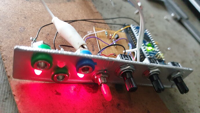
Working Clock Multiplier/Divider/Phase Shifter with tolerance for uneven clocks

Hey folks,

As the title suggests, I’ve been working on a clock divider/multiplier. Yes yes I know there are heaps out there, but with this one it has some oddities which are pretty interesting:

  • Based on Arduino and open source code
  • Can deal with slightly wonky non-perfect clock inputs fairly gracefully (ie non electronic clock pulses)
  • Has a phase-shifted output to allow you to move your outgoing pulses out of phase relative to the outgoing beat
  • A multiplier and divider that interact with each other in simple (power of 2) or complex mode(prime numbers)
  • The biggest most difficult part of this has been that it also allows for dynamic changes between incoming clock beats

So why would some of these quirky things be needed?

Well Sam (LMNC) had asked for a solution in Patreon to using his lovely phone exchange pendulum as a timing source to sync the whole museum together. The quirky problems are that it’s a very slow pendulum, and because it “recharges” the momentum periodically the clock isn’t perfectly even all the time.

This meant that classical approaches to multiplying/dividing this clock source meant that updates wouldn’t happen until the next tick which could be up to 2 seconds (depending on how it’s wired) meaning you’d be turning a knob and nothing would happen for a bit then pow we’re doing something unexpected because we didn’t have dynamic change happening. Also an uneven clock does some nasty things to most approaches to this making it not so pleasant to use.

So I wrote some code initially based on Atte Jensen’s a773 grains code for the ginko synthese grains eurorack module meant as an alternative firmware, but quickly realised that the base functionality wasn’t going to extend gracefully to deal with these quirks.

After a couple of weeks of spinning around in circles and revisiting the problem in a few different ways, I sat down with my friend Rohan and we nutted out this solution over 2 days with approximately 11,000 coffees. It’s about a 98% rewrite now and I’m pretty happy with it.

If you try it out, you’ll notice if feels a little more fluid than most clock multi/divs in that it tries to flow with a clock that isn’t perfect, and dynamic updates recalc on the fly which depending on when you do the change can throw the phase slightly as it catches up. I personally like it that way - feeling a little more organic.
EDIT: it appears that 100k resistors on the outlets is too miserly to trigger some modules, so switch them for 1k resistors instead - ill update this!

Here is the stripboard layout for now (I’ll make a PCB for it):

And Rohan is uploaded to his GitHub here:
https://github.com/RohanM/clock-with-shift

It’s a pretty tangled spaghetti of code, but it was necessary to fit all of those dynamic happenings in simultaneously. It also doesn’t suffer from accumulative drift which can happen with some simpler Arduino implementations as they’re quite slow, and simplistic delays can add up error as the loop spins but takes milliseconds for each loop around. This method uses a created waveform that we step through as the loop spins so we never lose sync with the incoming beats.

Let me know what you think - it was a wild ride. Look forward also to seeing how Sam goes with the pendulum as input!

10 Likes

Hey,

This is great. I finally signed up here specifically to thank you, after i saw sams last video yesterday evening…

The a773 module was literally next on my list of projects as i have an early 80s yamaha Pc100 keyboard i have circuit bent and im wanting to also get a clock out of it, but the only reasonable way to do so is by hacking off the timing LED which only flashes on the start of a bar, not the beat… So it can be reaaaaaallllly slow sometimes…

Since you have sorted this out im going to do it as a module instead since i tend to run the keyboard through my full diy modular anyways…

Do you also have a normal schematic floating about? . Id rather follow that when building since i dont normally use traditional shaped stripboards. If you dont, then let me know and ill draw one and you can check it before i build - looks pretty damn easy really, and in retrospect i could have done it myself jn the time it took me to compose this really long phone based post…

Im off now to post in the new members section. Im in Hobart, so not far from yourself…

Cheers
Cyclic

2 Likes

Aww! thanks!

Yeah I think that having something tolerant and able to gracefully cope with super long clocks that can also slightly vary is super useful. Most solutions I find get a bit quirky when things aren’t super precise.

Interestingly even from my microKorg I get sometimes a very slightly uneven clock when using internal tempo so when I was working on the final draft of this code with Rohan Mitchell we kept running into cases where even the microKorgs clock was throwing it out of whack with all of the logic we put in there to make it dynamically update between clock pulses. There is so much going on in that code now to deal with all of these edge cases it’s gotten quite nutty but works super well.

I haven’t designed it into a PCB yet so haven’t put effort into drawing a schematic, but it’s pretty basic, just some buffering on the input and some resistors to protect the outputs of the arduino. I’d suggest actually putting a switch on the simple/complex mode instead of a potentiometer, I’m going to update the code so this will then come in on a digital input too. Having a pot for a selection of 2 items seems a waste.

Also what might be handy is actually using a multi-switch instead of pots so you can “click” through the selections instead of a free spinning pot, but again this is probably all self preference.

Definitely able to check if you want to draw the schematic, otherwise I can whip up one in the coming days (got a few things on the go at the moment).

Great stuff! I’m in Scarsdale-Newtown which is a nothing place SW of Ballarat in Victoria between two forests - so not far at all (in Australian terms). I really love a great sound artist down there Dylan Sheridan - have you seen his stuff?

Keep in touch - I’m part of a group organising a pretty wild little festival next year in Melbourne if you’ll be across the water.

Jesse

3 Likes

Great job !

Me same when I saw the last video of Sam I also said to myself, this module will be in my next case :slight_smile:

Besides, I had taken a poor quality screenshot to have the stripboard, thank you for posting it.

2 Likes

Ok.

Hows this look as the schematic.

I wonder if the alternate i put buffer is a bit better. I ususally do it this way as it doesnt cut the input voltage by 0.7v and it conducts immediately kn reverse V rather than at -0.7v. Not really a big deal, but for a simple reorientation it seems worthwhile…

I guessed at the switch for simple/complex. Could pop an R kn either side but probably not important. Also seems like a very simple option for voltage control through a single transistor switch. But i dont need that so i wont bother…

2 Likes

This one is a bit easier on the eye:

I take it the pots can be any value one has available ( > 10k ) as long as they are linear ?

2 Likes

This sounds good @Cyclic - I haven’t bothered with going much further than a simple diode inline in the past without any issue, but you’re right it’ll possibly protect from reverse, though shorting to ground in reverse, will that cause problems for the sender? possibly need some resistance as well or something?

And yep not needed with arduino to chuck an R on either side of the switch, Arduino is fine without as we’re only switching its internally regulated 5V which it’s happy to receive unprotected.

1 Like

I always learned that it’s best to use 10k pots because of the way that Arduino measures analogue voltages, and that higher resistances cause it to take longer to achieve the measurement (something about a charging capacitor as part of the circuit) which in turn can slow down the speed at which you can reliably read that pot. So 10k is ideal, with higher pots you may find you start to get unstable readings, though thinking about it in this case, we’re only taking readings every 250ms, so it shouldn’t be a problem.

And yep linear is best, I was out of linear when I first threw this together and it was difficult to control. You could also do a multi-click pot (what’s their proper name?) with resistors to get the even points which would be more satisfying to click between the multipliers/dividers.

1 Like

Yes actualy you are right, id put in a series R as well for current limiting to protect the diode, and the diode, in sither orientation is rwverse voltage protection.
In my setup a reverse V will just ‘pull volts’ from gnd into the input device, rather than risking magic smoke from pulling them from the transistor or arduino…

1 Like

Fastest build ever!

2 days of minor thinking while completing previous project…
1 night failing to make dodgy arduino clones talk to computer…
Success after work day 2, then complete build started and finished the same night.
Works first time… Once i had sufficient input signal.

Thanks so much everyone. Now i can finally get my keyboards and modular syncing together after being on the project list for a year…

Cheers
Lance

4 Likes

haha nice work!

Yep the clones thing can be fun, but over the years (I use $5 ebay nano clones) I’ve learned that usually it’s just a matter of selecting that it’s the “old bootloader” option in the processor area once you’ve chosen nano as the board. Processors are processors so I’m never too precious about Arduino clones.

It’s a nice little module - I was using it to generate kick/snare just from a clock pulse the other night to test some stuff without having to program beats, just by shifting the shift output to the middle of the dial.

2 Likes

My clones got working easily in the end using a uno as the programmer. None of my computers would even see the nanos, the menu was greyed out - i wasted a night reading linux forums to fix it. … Plus of course, id inadvertently ripped the usb connection off this one and had to hold the usb socket in place manually which made it a dexterity as well as intelligence challenge…

1 Like

Ah!

Was it possibly a CHM (I think that’s the chip) USB converter problem? Sometimes depending on the system you might not have the driver for this odd chipset.

I see too you’re a Linux user? I’m a very long term fan (since the 90s) and have only used Linux on my machines since 2005. On my Ubuntu 20.04 machine I haven’t found an Arduino clone yet I couldn’t connect to.

1 Like

Possibly something like that… Im just a desktop user and use Linux on my ancient laptop in my workshop but Windows on the home pcs. I dont really enjoy programming or pc based music creation at all, that s why i first got in to making analog synths with real knobs - but i recognise that there is a lot of power in the digital if someone else writes the program and i build the hardware…

Bit of a correction here:

It seems that the clock outputs aren’t giving enough amperage to some modules that seem to need it.

I’ve built the Unauthorised Service Snare stripboard, and I’ve found that with this clock multiplier, it doesn’t get enough to do its job. Now I know I haven’t really gone over the snare that much yet, and perhaps there are things that can be tuned (though I feel like it might be the regulator itself not getting enough amps to get started), but looking at what I’ve done, I can see that 100k resistors on a 5V output (just something I did without thinking too much more beyond protecting the outputs) only delivers 0.05mA which feels very tiny.

Most other projects that use Arduino Nano appear to use 1k resistors which allows for 5mA output, for some reason I couldn’t find any here (travesty!) so I’ve chucked 1.8k resistors instead of the 100k resistors on the outputs and everything appears dandy again and I have my snare firing again.

I’ll update the stripboard layout unless anyone has any pointers or suggestions (other than using opamps on the output, I’m trying to keep part count suuuper low).

3 Likes

Yeah, the “standard” output resistor for modules is 1k, I think. A single Arduino pin can put out up to 40mA (200mA on all pins together), so you should be safe with a 1k resistor when you short the output to GND (and also against -12V, I guess? ~18mA?). :slight_smile:

2 Likes

Right, output impedance of 1k is common, and input impedance of 100k. Not an absolute rule but typical. 100k output resistors are way too large to drive a lot of modules. If you worry about how much current the Arduino can source you can buffer the outputs with op amps or transistors.

3 Likes

This is great to know - these kinds of little things are hard to find sometimes when getting into this stuff. It’d be nice to have this kind of info somewhere alongside the eurorack definitions or Kosmo definitions etc so you know what power things run on, the signal strength of CV and audio, and also just this kind of general interfacing info.

40mA per pin should be enough for most things per pin of the Arduino, some modules are super intense to build, I’d like to keep this one pretty basic in terms of hardware because the software was such a brain-burner.

Thanks!

4 Likes

@jessecakeindustries

Im not sure if you have seen this thread yet, contains a spec for Kosmo modules

2 Likes

Including, indeed, typical input and output impedances!

2 Likes