I don’t have anything that can output a clock (yet)
Does anyone have a simple but reliable schematic/strip that is suitable for use with KOSMO.
Cheers
Rob
I don’t have anything that can output a clock (yet)
Does anyone have a simple but reliable schematic/strip that is suitable for use with KOSMO.
Cheers
Rob
I can give you a simple but dont know about reliable one based on a 555 timer circuit. Might be better to use an arduino.
Yeah, I was in too minds about a duino. I thought about integrating it with the Baby 8 code but maybe on another build.
I lost all my sample code for my arduino projects when my SSD died completely on boxing day… But I know more than enough to cobble together an analog input for a POT to set the interval, and could also put it out to a LCD to display the exact interval.
I am going to build a front panel with Volt Meters for my Frequency Central PSU, so I will integrate the CLOCK on that front pannel 
Cheers
Rob
Reminder to self: Github and Bitbucket will back up your code for free. Please set up a hands-free backup sync asap.
Yeah… part of my day job is to ensure £MulltiMil systems are available and recoverable…
When you get home you revert to taking greater risks… Vitrtualy everything else of any worth was backed up. There was a couple of projects for my son with a lot of lines that needed re-writing anyway…
It was an anoying boxing day…
Rob
Tik tak is a simple but useful clock source + divider https://create.arduino.cc/projecthub/Synthemafia/modular-synth-clock-module-diy-arduino-sm-tik-tak-bd8ded
Use an LFO if you have an extra. Otherwise I could share my TokTik module. It’s similar to itsnot’s tiktak link, and only does 1 ppb but has two independent clock signals out.
Yes, always be sharing!
Well a couple of issues making TikTok Tick…
Built a sample of the circuit with just 1led and Jack for the moment.
1st Issue was encountered as there seems to be more than one “SimpleTimer” . The one that library manager installed was not right in any sense of the word…
So you need this one… https://github.com/schinken/SimpleTimer
Second issue was that the USB cable I have seems dodgy on the data lines so the serial port was not always showing…
And then when I got the code uploaded the LED was very very random. So I was in the process of just testing a basics Analog read and print to the serial port… When one of the pots started smoking. Interesting!! I snipped it out, changed the main code as the suspect pot was the interval one so needed to swap it the easy way with the duty Cycle one…
And with that done there was a reasonable clock. I think these pots must be fairly garbage as the remaining one was seemingly afected by simple movement of the device!!
Anyway, it’s a start and it’s proven in basic terms…
Thanks for the input.
Rob
Not much to look at yet…
I got a bunch of new nanos so started a permanent build…
But when I tested it, it was garbage, input was not good, output may work, totally random… Only seemed normal when I touched the dunno… I was seriously hacked of with this simple circuit…
I reviewed the diagram, and remembered I had not bothered with the rest switch or its pull-down resistor on D10… It was too late last night for me to bother trying that…
2 mins this evening, pull down in place. …
Nice solid reliable output
Now time to finalise and upgrade 
Inspired by my success, I fitted a display…
1St power up resulted in smoke…
2nd power up no USB serial… Not on another dunno, not on another port… I was using a crap power only cable!!
3Rd power up… Code on. No display…
Adjusted the contrast and hey presto…

Fuck yes. Good powering through m8. I might give that a try too!
The code mods to do the display are a few lines, nothing at all tricky. and the wiring to the display is also just 4 easy connections.
I have never had to bother with the Pull-Up resistors before as Normally use UNO’s and always set the pullup if a pin is even possibly going to be in the code. And Since I did not write the code I had not thought about the effect of the reset floating about…
For what it costs in time and effort It’s worth having arround…
Rob
TwinTurbo (MCUK)
BTW for anyone who’s interested, the Arduino Micros are dirt-funking-cheap right now at the Arduino store, and they ship in no time. They use the old 32u4 instead of the Micro’s 4809, which gives me (at least) different results for different purposes. The 32u4 is to one to use for capacitive touch applications, while the nano has an extra pair of ADC inputs. They’re nearly pin-compatible (nano is missing a column I think.)
Seeing the genuine deal be 21 buckazoids really opens my eyes to the value im getting for the $4 fake boards im getting.
They’re open source hardware and the software platform is open source, too, so the term “genuine” has little real use except to guarantee that your money will go towards maintaining some kind of order and direction in the project. My first Arduino was a Sainsmart that came with a whole experimenter kit, and it also has a neat 5V/3.3V switch.
You can run Arduino software on a wide range of AVR chips nowadays. That’s great for when you want to develop on a 328 or whatever and then scale down to a much smaller chip. That’s mostly for people doing through-hole construction; the surface mount chips are quite compact.
It occurred to me today that I could just go ahead and wire up a large oscillator bank with Attiny85s. The details would need to be worked out, but for PWM this would be very feasible. They could even repatch each other on the fly over one of the serial communications protocols these tiny chips support. For DAC usage I might have some kind of multiplexing scheme so the signal mixing takes place at the digital level. And if you’re only using two chips from a bank of 20 the other 18 can be sent to sleep drawing minimal current.
I’d be really interested in seeing how this works out. I think someone pointed out in another thread out the digital outs are in essence an analog square wave, but PWM in that scheme of things could be very dynamic-even voltage programmed (ie, 1pulse/duty cycle/volt, etc.)
Pulse width modulation (PWM) and related schemes such as Pulse Density Modulation are very versatile ways to encode an analogue audio signal as a series of pulses. The interesting thing is that, just as with the modulation schemes used in analogue broadcast radio, decoding the signal to audio is remarkably easy to accomplish. AM radio just needs a rectifier, some pulse-based encoding systems just need an RC low-pass filter. The only issue in both cases is ensuring adequate fidelity.
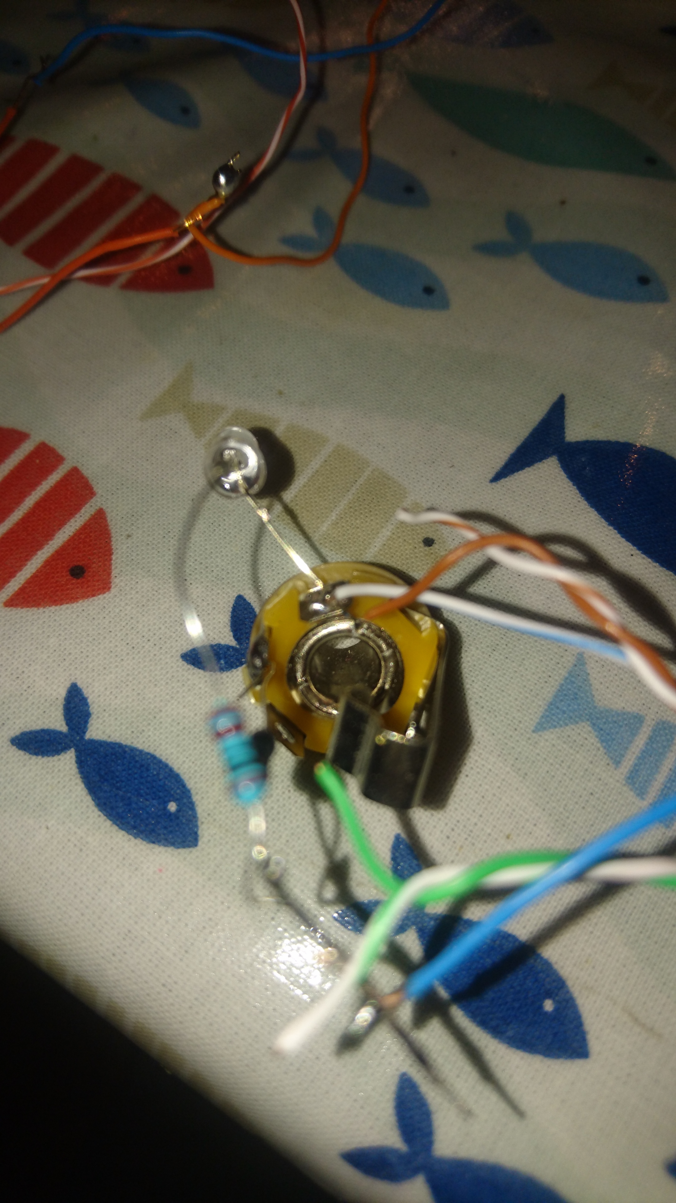
It’s been another battle with this simple circuit.
I elected to use very fragile single strand solid copper wire which does not help.
After building up on the panel the BPM pot was causing issues, I spent ages replacing, testing, etc… Eventually found the A0 pin seemed shorted to AREF, but the strip board was well glued down by this point
I just bent the pin so it was not in the socket. I has something similar with the duty pot being odd… And just gave up and fudged the value in the code
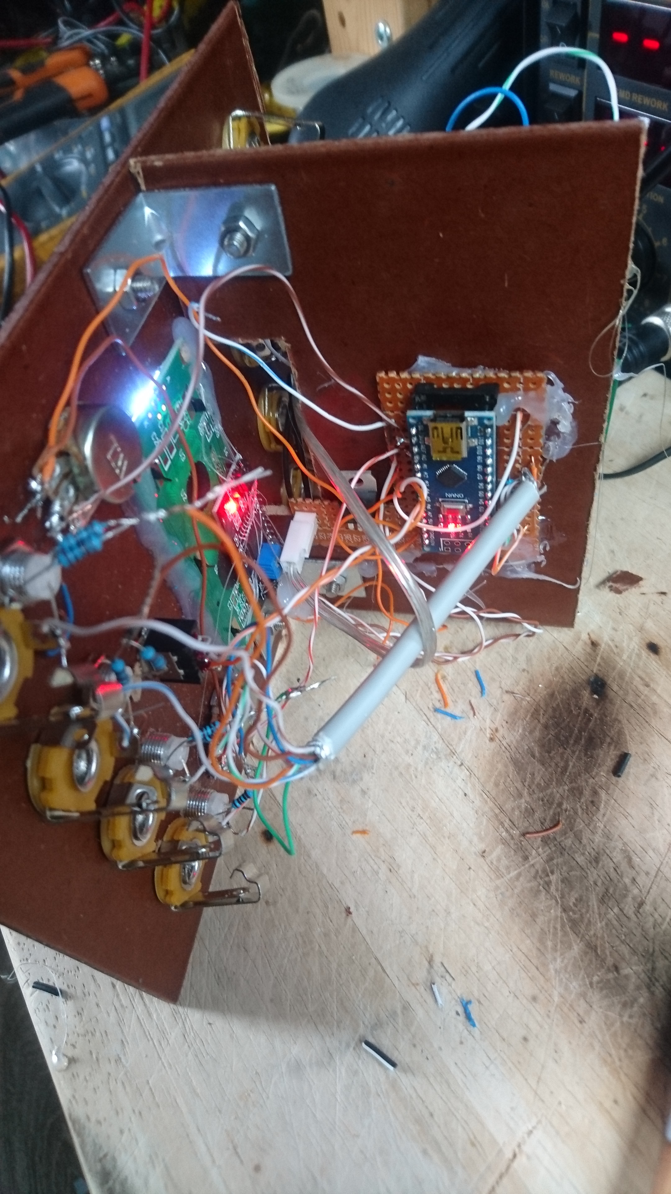
I also had spare space so put on two very simple VCO… It’s not at all nice on the other side. I consider this version V0.1
It may not be super neat in v0.1, but I like the angled panel material mount for holding circuitry!