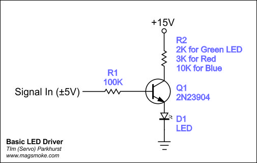
I am modding a tremolo/ring modulator guitar pedal for a friend. The pedal has an external LDR which can be set to control the LFO rate. Since he asked for an external CV input to connect with his modular synth, I thought that a no frills modification would be to move the LDR internally and connect it to an LED that can be driven by external CV. I breadboarded a simple LED driver using a 2N3904 and it works as needed: the LDR responds nicely to CV from my synth’s LFO, gate, and env outputs. The problem is that I hear the ticking rate of the LFO. I know that I am supposed to add decoupling capacitors to reduce the ticking, but I am not sure where to put what in the circuit.
I’m not sure but could the ticking be caused by the transistor being completely opened by the LFO because the LFO voltage is too high? I’m thinking the LFO might be clipping itself, so you do not have a gradual rise and fall of the LFO signal but the signal might have a flat top (or bottom), which may produce harmonics in the modulated signal.
Note: if your control signal is negative, depending on the type of your transistor it could get damaged, so I would in any case add a diode between the 100k resistor and the transistor’s base. Symbol of the diode should be pointing in the same direction as the NPN transistor symbol.
To test whether the LFO voltage is too high I would suggest you add a potentiometer to try whether a lower input voltage will be sufficient to get a proper VCA effect.
To find out which voltage you need on a trial basis you can also substitute the LFO by a potentiometer with one side connected to GND, and one to 5V and use the ruler as control voltage and try whether the VCA works as you would want it to. Using a voltmeter you can measure the voltages on the potentiometer which make things work so next you can try to work out how to get your LFO to produce the same voltages.
After reading my initial comment I had a look at the datasheet. According to a datasheet I found the max V-emmitter-to-base is 6 Volt, so if your input keeps within -5 V to 5V, you need not add a diode. But if it doesn’t I would put one between GND and base with the kathode connected to the base (arrow points from GND to base so to speak) so that it will conduct whenever the input voltage is (sufficiently) negative.
Have you tried to find the LFO voltage needed to open the transistor properly, e.g. by using a potentiometer ?
Thank you so much for taking the time to troubleshoot this for me. The transistor looked fine without the diode, obviously because everything was within limit. However, since my friend could be plugging it to all sort of weird things, I decide to add a diode just in case. I initially added a 4148 diode from the resistor to the base (not ground) and it worked fine. Then I added 220μF and 100nF decoupling capacitors. It turned out that the ticking that I heard was not from the LFO but from the ring modulator itself, so everything was fine. The capacitors did not make a difference, but decided to keep them just in case. So I built the thing on stripboard. However when I tested it before boxing it in the pedal I got another problem. The LED remained on and was only very faintly responsive to the signal. I check all the joints, the traces, and removed the capacitors, but the problem persisted. Thd circuit worked fine on breadbord but not on stripboard.
Where did you add these? Especially the 220uF capacitor could keep the transistor open for a long time if placed strategically (but not correctly).
This is a bit of a guessing game because I do not know how you positioned it but if e.g. the 220uF capacitor loads via the transistor but does not unload, it will keep its charge for a long time and may be biasing the transistor ‘permantly’ so that it always opens (a bit).
If you don’t need the caps, leave them out. This makes it easier to understand the circuit later when you look back at the design. It is never wise to add stuff that you don’t understand the exact working of. B.t.w. 100k as a base resistor is maybe a bit large, you could get away with a smaller value (like 10k) as well. That will probably make the dynamics of the LED larger (difference between dark and light).
There are 2 potential causes: it did not work properly on the breadboard in the first place but looked like it did and when replicating it on a stripboard the error manifested itself more clearly. - This may sound silly, but you should not discard this possibility beforehand. Can you build it again on breadboard and does it work like the 1st instance? - Or it does not work properly on the stripboard. Anyway, there must be a difference in the wiring or the components’ condition that explains the difference in behaviour.
Thanks again!
This is what I built on stripboard. I thought that the charge of the large capacitor was responsible for keeping the LED on but the problem persisted after removing the capacitors from the stripboard. I will give it another go on the breadboard and report the results.
It looks like the caps are connected to the powersupply, so they will not affect the LED. D1 should be connected from the GND to the base of the transistor (white band connected to the base, black part connected to GND). To experiment with a lower base resistor you could try a resistor of say 10k simply by bridging the 100k with that (by hand). If that works well, remove the 100k and solder the 10k in, otherwise no soldering needs to be done.
The diode needs to have the white stripe end connected to the base and the other end to ground, not collector, and the input needs to connect to base, not collector. (Transistor pins from top to bottom are collector, base, emitter.)
Good catch, thanks @analogoutput ! It appears that, in the stripboard, I did not only connect the input to the base as I should have, but also to the collector. I should also correct the diode placement though. However, shouldnt the diodes be reversed in both schematics?
Facepalm moment. It should be the other way round in my build. I mixed up the 4148 black stripe for what appears as a black stripe in the layout. What I get when trying to finish something at silly am!
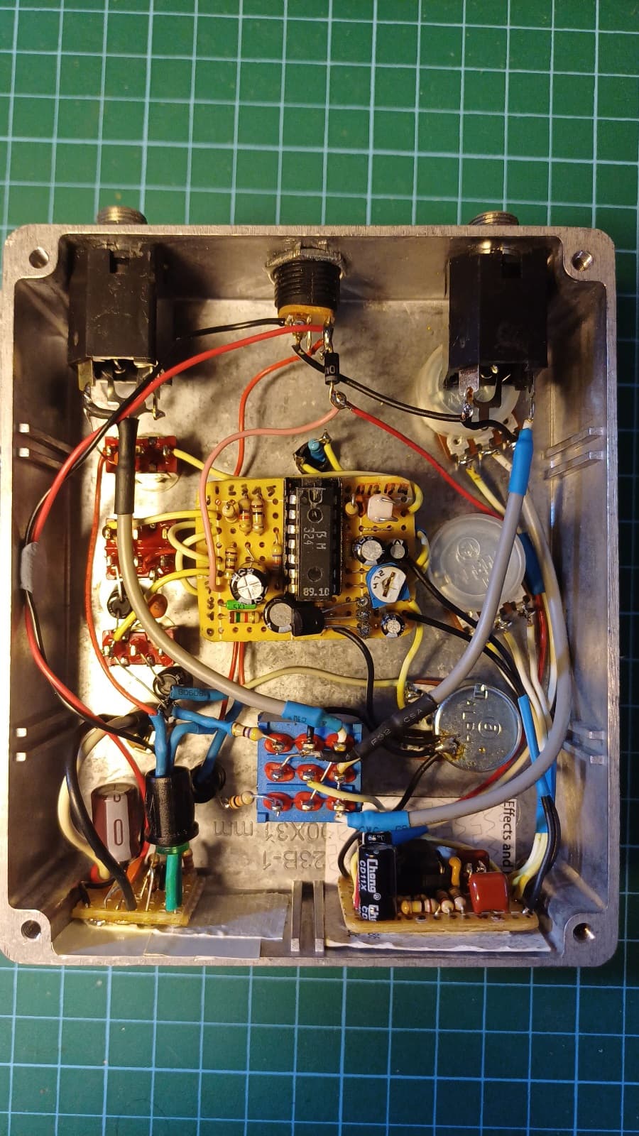
With thanks to @Jos and @analogoutput for the advice and for spotting the errors, the job has been completed. I tugged the circuit at the bottom left and, as there was no drilling involved, the pedal can be easily restored back to its original state.
 Thanks again!

