My most recent modules I’ve breadboarded first, even if I wasn’t planning any mods. Partly to verify the circuit worked, partly to check any part substitutions, and partly to see if the output levels, frequency ranges, LED brightness, et cetera were what I wanted and would not need tweaking. (Things that the designer might have wanted different than I.) Probably not necessary most of the time but I feel like it’s a good thing to do. For me.
Of course that’s THT circuits. If you’re building SMD then there’s a gap between what you can breadboard and what you’ll build.
If I were in your shoes I’d probably breadboard this with THT components, including 2N3904 transistors to stand in for the MMBT3904s, for the above reasons. But I think it’s unlikely anything would come up that would need changing, so I’d say skipping the breadboarding would be probably fine. (But not if you were to change the LEDs as @eric suggested.)
Thanks @analogoutput . I understand breadboarding is what I should be doing and verifying everything beforehand is the smart thing to do. I don’t know how to breadboard and I don’t have the time to learn anytime in the foreseeable future. If it’s likely that everything will work with this other transistor then it’s worth it to me to just get the boards made and try it. If it works then great. If not then I’ll probably go to plan B of purchasing some already made modules. I have so much left to do and time is not on my side.
There’s pretty much nothing to learn. You get a solderless breadboard, you stick components and jumper wires (cut and strip solid core wire, or buy these) in it, done. Figuring out the layout? You do that from the schematic on the fly. Let’s see, this resistor needs to go from that pin to a capacitor which then goes to that pin, okay, it’ll fit over there… And if that turns out to be a bad site for the capacitor, no problem, you just pull it out and stick it in somewhere else.
Really, it’s dead simple. For this module (or half of it really) it’d take maybe ten, fifteen minutes. Longer if you want to be neat and orderly about it, which might be worthwhile if you’re developing a circuit and need to work with it a while, but just to test an existing circuit don’t bother, a rat’s nest will still work. And it saves a ton of time compared with PCB trial and error.
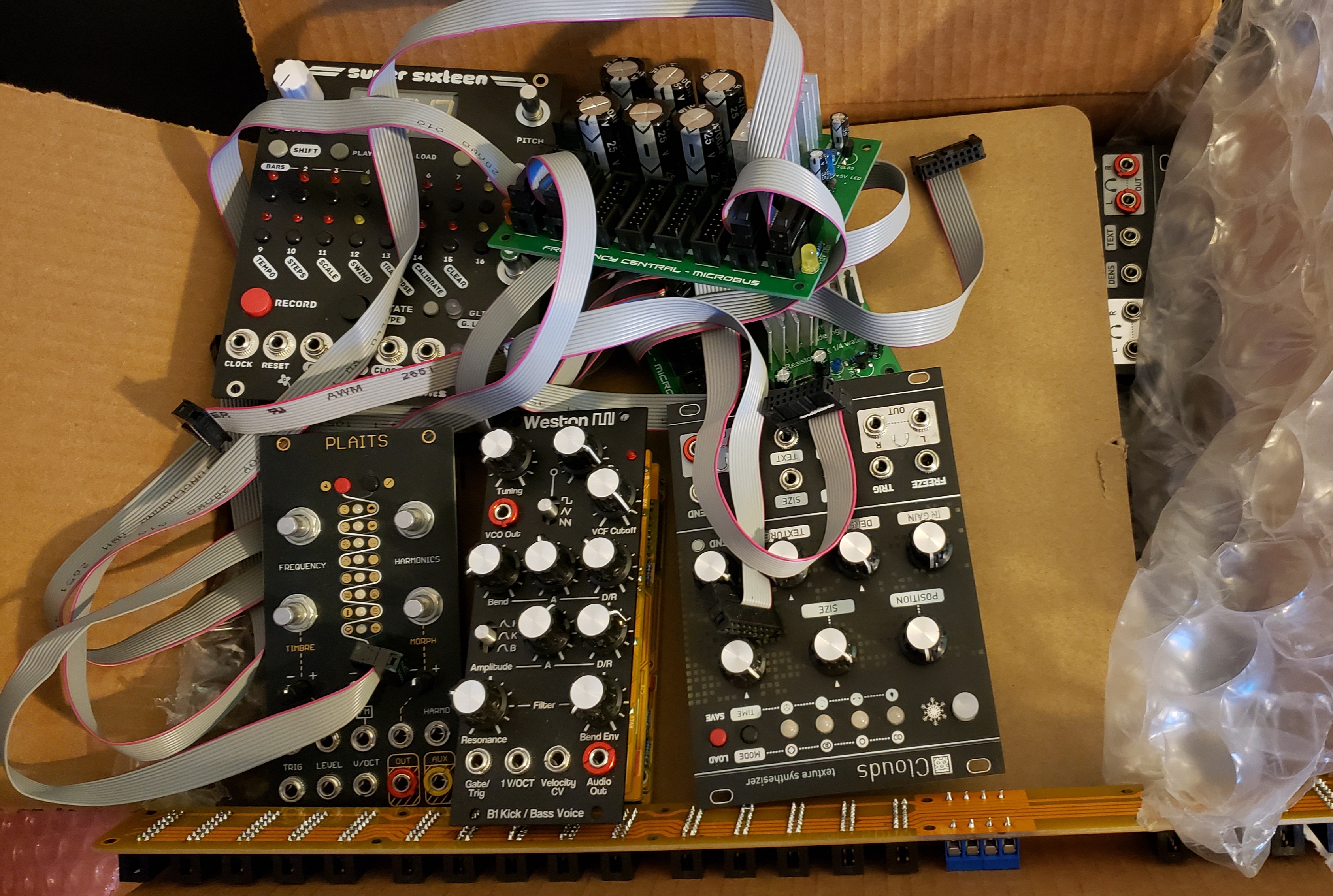
I understand. I have a couple of breadboards that I got a while back and I already have some of those connectors that you linked. It’s figuring out how to power it, hook up the jacks or pots if needed, leds, and trying to figure out the schematic. Schematics do not always make sense to me. So it’s just not that simple for me. I also would not easily be able to test it if I was able to fully breadboard it because I still am not 100% sure how to use a modular. I haven’t been able to play with anything much to figure it out. Currently, this is what happens to my modules since I literally have zero time to make a case. Pretty frustrating.