I have been looking, for quite some time, to find a filter that I could use with synthesizer and guitar signals and/or for quick circuit-bending modifications, which has the following characteristics:
- 9V supply
- Resonance control
- CV input
- No expensive or hard to find parts (e.g. OTAs, Vactrols, photo-FETs), or parts that cannot be replicated reliably (LED/LDR combinations)
- Ability to apply easy modifications to suit different signals, and/or to alter its frequency response, and/or its overall sound
- Fairly low parts count
Initially I looked at a discrete low pass circuit proposed by Antonio Cavadini (aka Tony Light) in 2009, but I found it difficult to add a CV input or modify it otherwise. Moreover, the requirement to use a stereo potentiometer was pushing it a little in terms of easy to find parts.
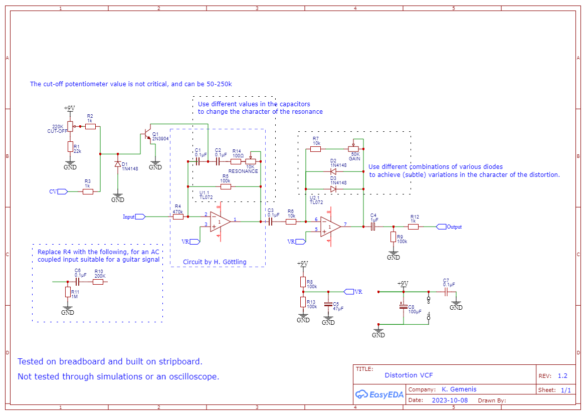
I then turned by attention to a design proposed by Hendrik Göttling back in 2010. Göttling’s circuit bears semblance to the second circuit in Tim Escobedo’s Q&D, but most values have been changed, and the circuit configuration turned into that of an inverting op amp. If you factor in the CV/frequency input resistor, the filter topology is essentially a “bridged T” with the positions of capacitors and resistors reversed which, as Rod Elliott suggested, should give a notch response just like in the typical non-reversed version. Jack Orman noticed that the tone control of the “Big Muff” fuzz pedal is essentially a typical “bridged T” notch filter, but the advantage using a reversed topology as proposed by Escobedo and Göttling is that you can get very prominent resonance by varying the resistance next to the capacitors of the filter network. Moreover, CV is implemented by using a diode as a crude variable resistor.
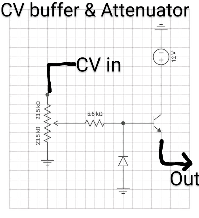
An drawback of the Escobedo and Göttling circuits is that the frequency sweep of the filter is very narrow, especially when using a CV. Uwe Schüler (aka elektrouwe) suggested that in order to increase the frequency sweep of the CV you need to decrease the CV input resistor. However, since the CV input resistor runs parallel to the frequency resistor, you need to isolate the impedance of the CV-source from that of the signal, and suggested to replace the LED (Escobedo) / diode (Göttling) by two diodes in series and connect the middle of the two diodes to the capacitors node. I found that I could further improve the frequency sweep by using a BJT transistor instead of the diodes and a larger potentiometer together with a series resistor for the frequency cut-off. This comes at a cost though. The cut-off control becomes a hybrid cut-off/CV amount control when one uses a CV.
Having established a low parts VCF circuit with satisfactory results, I sought to add a few modifications of my own to give this VCF extra character. The first thing I addressed is the inverting op amp configuration of the Göttling circuit. I thought it would be better to have a non-inverted signal at the output. Most people use dual op amps, so I used the second op amp in the package as an inverting amplifier to invert the signal again, and while at it, add some distortion. Distortion sounds much better after (resonant) filtering that adds harmonics to an otherwise dull synthesizer waveform. My choice of distortion was to add clipping diodes in the feedback loop of the op amp, as in some sort of reversed “Big Muff” (filtering and then clipping the signal, rather than clipping and then filtering).
The modifications to the original circuit required the addition of a few, easy to find, extra parts but added plenty of character to this VCF. Moreover, one can explore more options in the clipping diodes (symmetric and asymmetric combinations of different diodes, resistors and capacitors) to introduce additional subtle variations in the tonal character of the VCF, and/or change the character of the resonance by tweaking the values of the two capacitors in the “T”. The combinations that sound best can be added as options through (rotary) switches making this a very tweak-able VCF.
I haven’t put this through an oscilloscope and I haven’t done any simulations, so let me know what you think or how this could be possibly improved.

Edit: corrected D1 placement.


