hi people,
here’s the latest episode in my filter design series. this time, we’re building a three pole diode ladder filter (though it could be debated if that is indeed the right name … ah semantics). it has nice smooth resonance and is very stable (unlike some other diode-based implementations)! let me know if you have any questions & thanks for watching!
@moritzklein thank you a lot for your great work sharing, this is very helpfull for all the diyer community! I LOVE your tutorials, better serie than Netflix !!
I advise everyone to support him on his patreon page, nice surprises await you !!
Im studing your diode ladder filter version, and it look nice!!
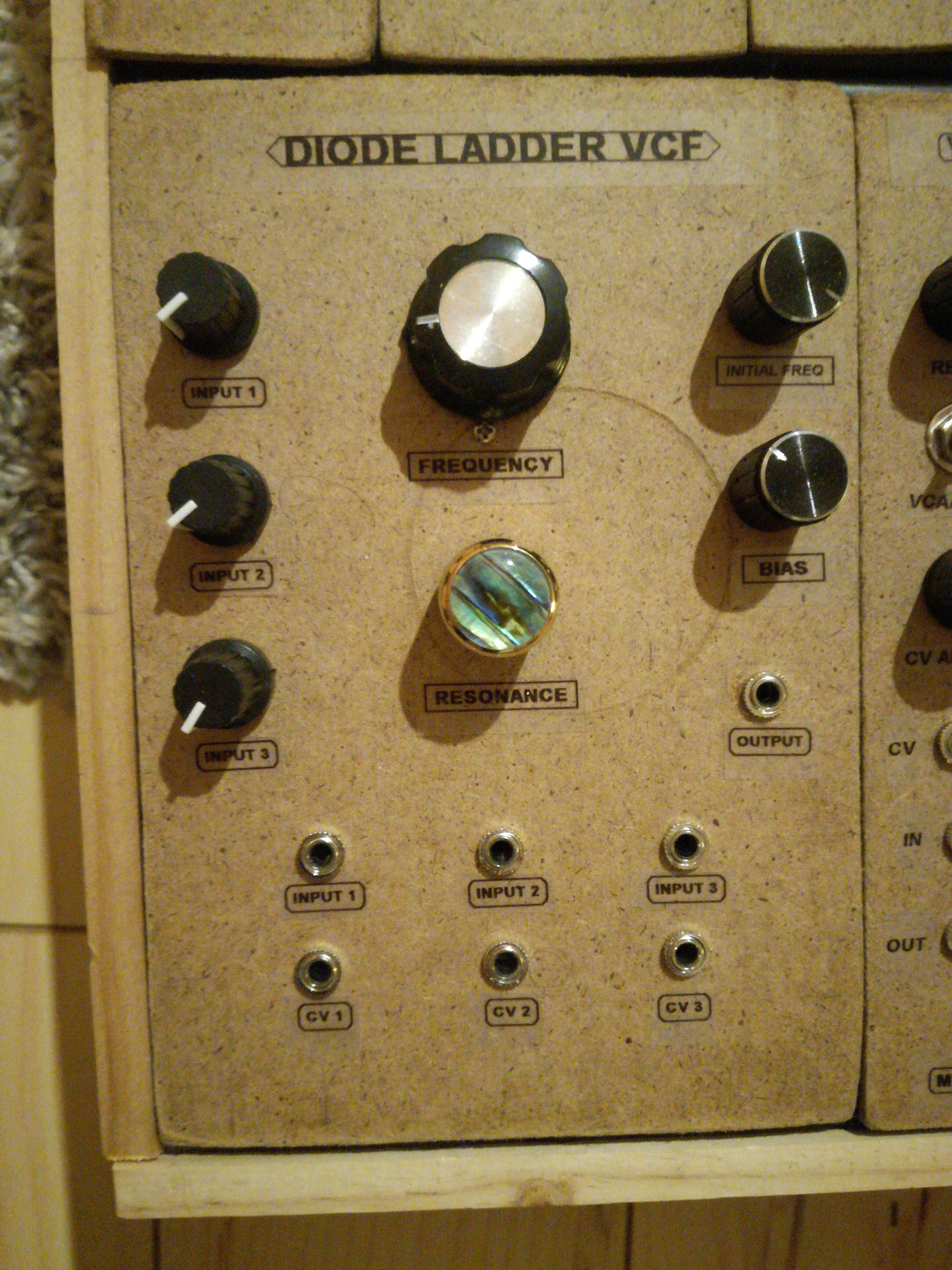
Recently, I have build a 9v version of an diode ladder filter by Tom Gamble which looks pretty much like this one, but with multiple cv and audio inputs !! I like it so ! (I suppose it can be working with 12v too)
Here the schematic:
unfortunately i can’t really draw it by hand (doesn’t really fit on one page). but here’s a complete simulation on falstad: https://tinyurl.com/y7eftwyz
mine feels like it’s on its last leg unfortunately – LFO starts modulating things randomly and spontaneously, headphone output has loud ground noise… sad!
it’s basically just 10 4-bit shift registers chained together. i then selected three LEDs where i attached basic gate-to-trigger converters. so the idea is that you can send in bits (either manually via a pushbutton or through an external input) and have those circulate through the registers. every time a bit passes a gate-to-trigger converter it fires. so something like a sample & hold for rhythm! you can also choose if you want it to loop and from where (after the first 4, 8, 12, 16 … bits).
almost perfect – there is one 22k resistor in there that should be a 33k! also i noticed that for some reason the resonance sounds nicer with a 100k/27k combination instead of the 10k/2k7 in the resonance op amp’s feedback path!