I have several TFT displays with parallel interfaces, but the i2c screen used in Scope-O-Matic has its own controller and the small number of data lines makes it not only very easy to use it but also uses up only few resources of the Nano. So there remain more for the sampling process. Those are nice virtues I could use in my next project.
4 Likes
Yes, it’s really in the sweet spot. The display is small but usable and it doesn’t hog scarce resources.
4 Likes
I have to say my plan to use an old android phone running scope sw and a modified USB soundcard velcro’d to a panel is still going ahead. Bit I’m building this too.
5 Likes
After some more thought, this could become complicated as this would imply at least one delay function and you wouldn’t want to disturb the interrupt based sampling. So probably a hardware solution was easier.
1 Like
I found a nice reference about displays, all kinds of displays. And per display a ton of info about how you can connect it to an arduino, raspberry pi etc. It is actually a wiki, aptly called the LDC-wiki. So if anyone would like to hook up a display different from the one I used in Scope-O-Matic, have a look at that wiki page.
4 Likes
pcb and mulit purpose panel IS in progresss,
5 Likes
Ha, looking forward to this. If you need any help with the software, let me know.
3 Likes
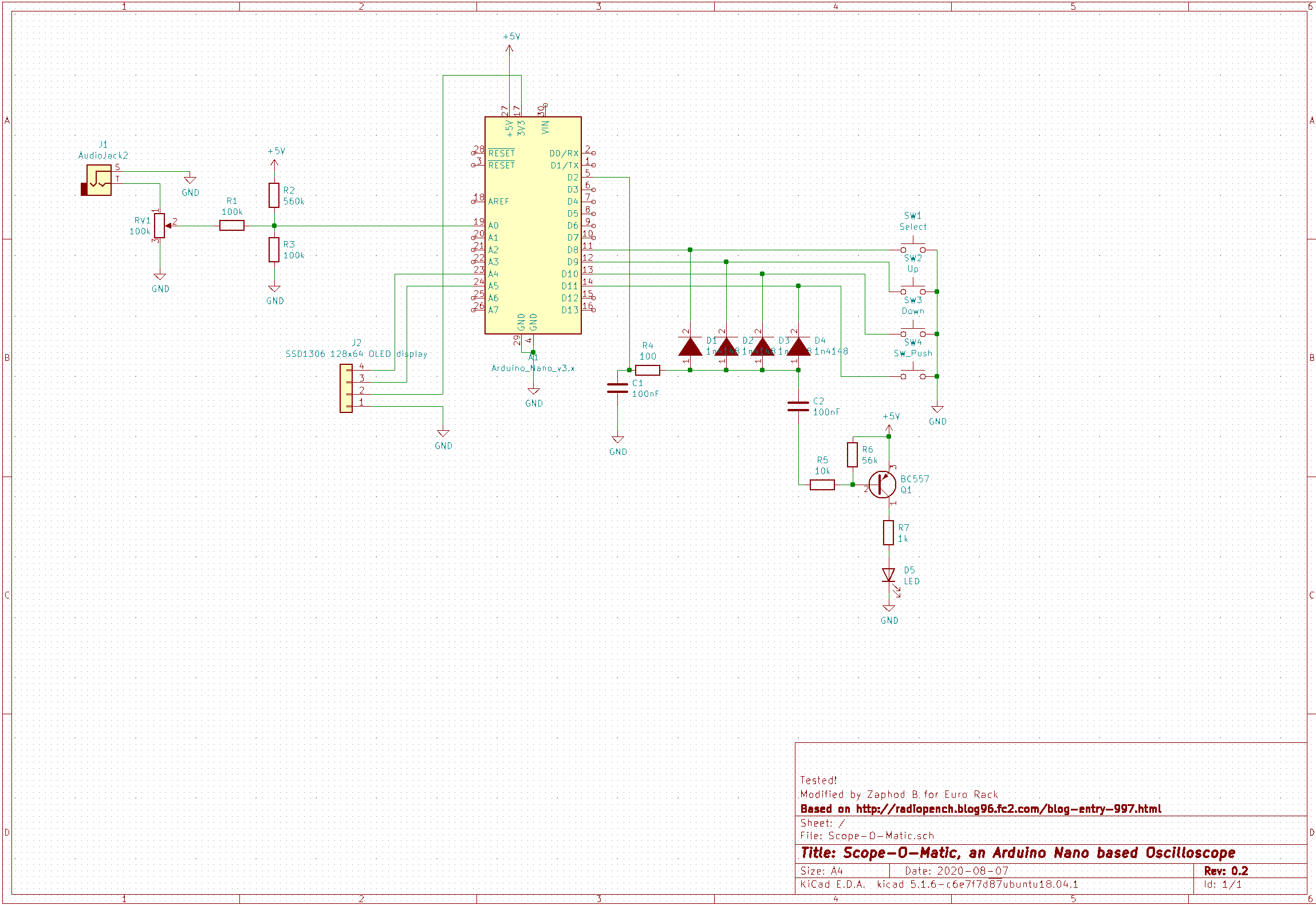
I noted that the SD1306 OLED display is sometimes listed as suitable for 5V, sometimes for 3V3. Some info says it runs on 3V3 and the boards have a level converter on board. I could not identify a level converter on my boards (which does not say there is none!). In the Scope-O-Matic schematic so far the display was hooked up to the 5V supply line and my instances have been working for a few weeks without a problem. I tried then with 3v3 and that worked fine. So, just to be on the safe side, I rewired both of my scopes and changed the schematic:
@twinturbo you may want to have a look at this and maybe change your pcb layout.
2 Likes
At 0.96inch OLED Module MC096GX - LCD wiki it says:
Wide voltage supply (3V~5V), 3.3V and 5V level logic compatible, no level shifter IC
and in the schematic it appears VCC goes to an XC6206 regulator to produce 3.3V which is used everywhere. Both OLED units I have (appearing to correspond with MC096VX and MC096GX) have an XC6206.
So I think 5V should be fine.
3 Likes
There is a lot of contradictory information on the net, so I rerouted only one connection and thus avoided any problems.
3 Likes
Yes, the low dropout of the XC6206 means it outputs 3V with 3.3V input and that’s good enough, so VCC from 3.3V to the rated maximum of 6V can be used.
1 Like
But does it support 5V on SDA/SCL when powered from only 3.3V ?
(I don’t wan’t to scan thru the datasheet if somebody already did it…)
1 Like
Yep, that’s what “5V level logic compatible” means ![]()
And even if it wasn’t compatible, as I2C use open collector transistor you could’ve just added two clamping diodes to the 3v3 rail (and that’s probably what they internally do).
3 Likes
Well as I stated, I’ve rewired the displays and both work. The nano uses 3V3 as far as I know, so that would be another yes. This is a relevant datasheet for the display, but it may have been mounted on a different PCB depending on the manufacturer.
2 Likes
There are two versions of Nano (well, much more… but we are just interested in the difference of running voltage here)
The one where the atmega runs at 3V3 is limited to 8MHz (and all I/Os are 3v3),
while at 5V it runs at 16MHz (could even run at 20MHz IIRC)
From the reference design, it looks like the 3V3 pin is powered by the USB chip, not a separate regulator (5V has a regulator), so I have no idea how much power you can draw from this pin (I know, read the datasheet… but : - not all Nanos use the same chip, - I’ll find out by experimenting  I have done several Nano project and never reached that limit)
2 Likes
If anyone is interested in a burn out test video for these OLED displays, have a look at this:

Edit: if your Russian is a bit rusty I suggest you switch on subtitles and have them automatically translated.
4 Likes
I can pop in a jumper for voltage select, it’s no issue.
I drew out the foot print for the display today which will help with the PCB and panel layout.
Been a bit slow on this but it’s not far off.
Rob
4 Likes
A wise man once said: “You can never have enough VCAs”.
True, true, but I would like to add:
“and each rack deserves its own oscilloscope”.
So I made another one (yep, I’ve got 3 racks now), this time with a multi color (blue and yellow) display.

The dual color display is divided in 2 regions. Only the upper few lines of pixels are yellow, the rest is blue. This makes the menu items stand out in yellow while the signal is shown in blue.
If the positive signal amplitude is very high, its peaks will be shown in yellow, which works as sort of a peak detection. I was advised by my marketing department to say that a lot of thought had gone into this during the design process.
9 Likes
Hi,
stumbled across this project via a google search and want to have a go at building this 
But…I wonder if there is a later version of the schematic - the versions I see here and on github only have a single LED, but the photo’s have two and are described as one for when a button is pressed and the other when the waveform is triggered. Where can I find how the triggered LED is wired?
Thanks
Texy
1 Like
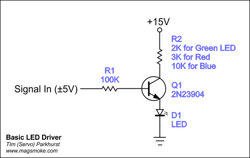
To add aled you can add this type of circuit.
Signal connected to the Trigger jack, +15 or +12 V and a 1 K resistor for the led must be well