Hi!
Im waking this thread again since I have some trouble with my vco. I first built the one with pwm and square out, but that one didn’t work so I thought I would build the basic core model and get that one working first!
But the simpler model don’t work either, I have measured the voltage from gnd to pin 3, as well as pin 16, as told above, and everything looks good there, when I plonk the module in I get a clicking sound from the saw out, and a similar slow klick from the triangle out but in a much lower volume.
Here is the click from the saw out: Vco problem klick - YouTube
I am using the as3340 chip
Does anyone have some ideas of what the problem might be? I’m attaching some images aswell…
Hi, the difference in volume is normal with this layout.
It sounds as if you are using a short decay on the input. On your video, what is the configuration? Just the output plugged into your mixer or console or whatever you use…? What happens when you turn the frequency pot ?
Sounds like it’s oscillating but at very low frequency (~0.5 Hz). In which case maybe the control voltage is much lower than it should be, or I’ve also seen similar problems when the linear FM pin network isn’t right. But that’s just two resistors to ground and 12 V in this simple version and those look right to me. So check those but if they’re OK then the question is what’s the voltages at the top of the two 100k resistors connected to pin 15, as shown here Annotated Simple 1V/Oct Oscillator Stripboard. I think they need to sum to something like 9 V or more to get an audio frequency signal. And check that one of them does change when you change the tuning pot. Also verify the 470R to 10 nF to ground from that pin.
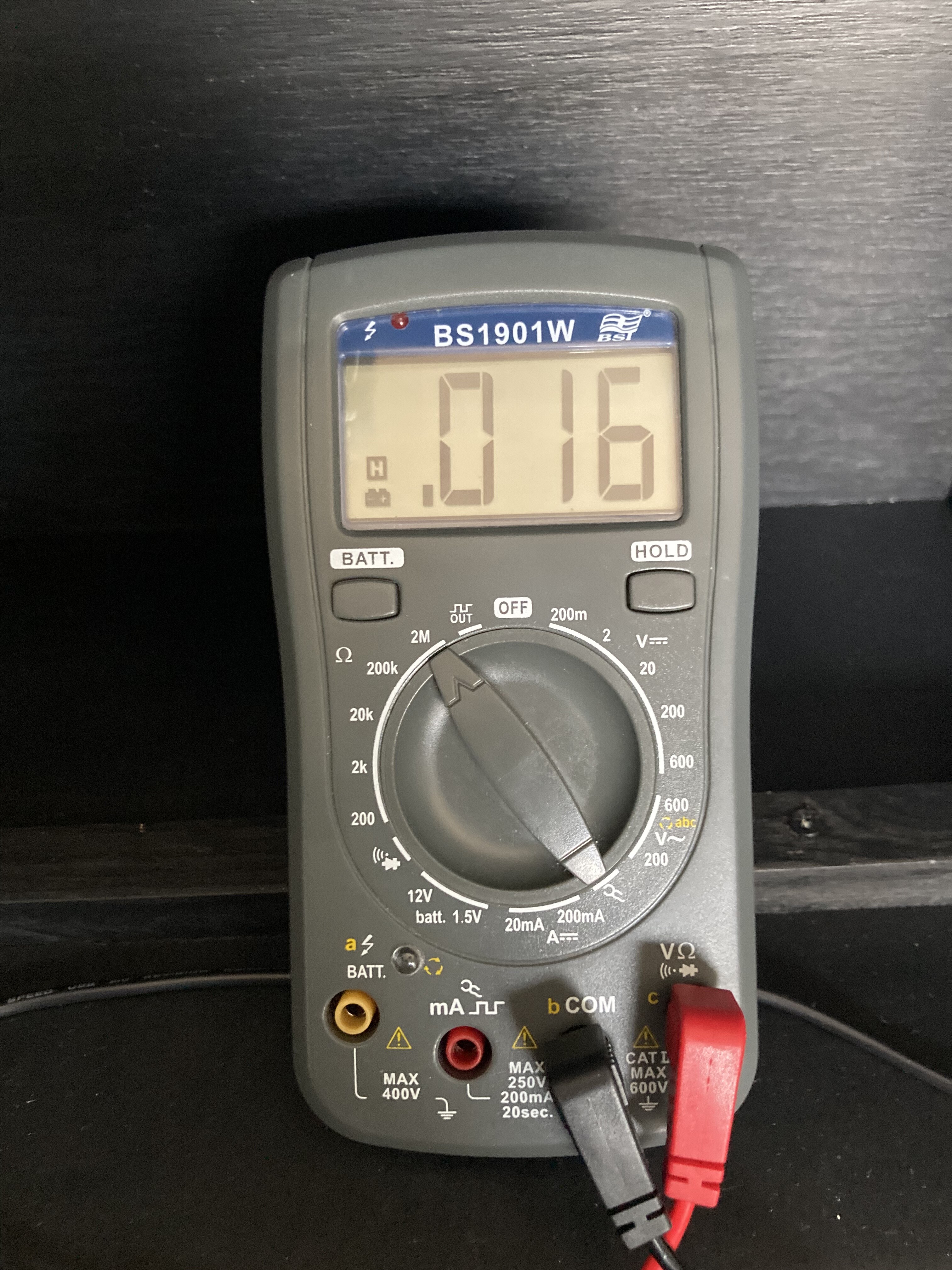
You cant really check the values of most resistors once they are inside the circuit (they compensate, depend on each other). That being said, if you get 0.1 where you supposed to have 1.5M, then yes I also think that it is an issue.
The 1.5M resistor connects directly to +12V and pin 13, not in parallel with anything else external to the chip, so my guess is it really should read 1.5M. The color stripes on yours appear to be brown green black yellow (150 0000) which is correct, and it’d be very surprising to me if it were really 0.16 Mohm (and totally astonishing if it really were 0.16 mohm, and equally astonishing if you could measure that) but I suppose there’s an outside chance it’s mislabeled.
It forms a voltage divider with the 470R resistor. Assuming high impedance at pin 13 it should divide 12 V down to 12*(470/1500470) = 3.7 mV. If it actually is 0.15M then that would become 12*(470/150470) = 37 mV. And I think higher voltage on pin 13 sends the pitch higher, so I wouldn’t think that would cause you to see much too low frequency as seems to be the case.
You see +12V at the top ends of both resistors? That should send the frequency to the moon. I don’t know why you’d get 0.5 Hz clicking then. But you could try disconnecting or lowering your CV, if it really is 12 V. It doesn’t need to be that much. Once you calibrate, 0 V probably should give you a note near the bottom of the bass range and 12 V would be 12 octaves higher, which is pushing dog whistle territory.
But you say your tuning pot isn’t working, so that’s also +12 V, and that’s not helping any. If you check voltage directly on the pot, from the wiper terminal to ground, is that also +12 V and not varying? It definitely should not be. Something maybe is shorted to the +12 V rail.
I think I must have done something wrong yuesterday cause Im measuring totally different values today when I remeasured, maybe it was just me being very tired yesterday. Since Im really bad at reading the multimeter I thought I would share some pictures of my measures…
Are these numbers making any more sens?
Am I just an idiot and putting the multimeter in the wrong settings? I haven’t used a multimeter up till this point in my life so that may be the case!
One more thing to mention is that i noticed the voltage on the 100 k cv/cv tune resistors bump up a little when the click was heard.
I’m very thankfull for the help I am getting since my electronics knowledge is very limited, I am learning a lot from you guys!
You have only 261 mV on the tune resistor and -4 mV (really 0, presumably) on the CV resistor. I don’t know what CV you’re putting on the input, but the big problem is you have 6 to 12 V on the tune pot but it’s not getting to the CV resistor. Check those connections. With power off you can use the continuity setting on your multimeter to verify whether things that are supposed to be connected are, or things that aren’t aren’t.
It’s very weird though. If you had 0 V on the resistor it’d presumably just be a bad connection, but how do you get 261 mV there?
Just to verify, you’re measuring from this point to ground?
Plugged in my beatstep pro to the cv input jack, and i got it to play a melody, (don’t know why that idea didn’t cross my mind before…) checked the connections to the tune pot and I everything was fine. Then I tried soldering on another pot instead and everything works as it should! Must have been a problem with the potentiometer … Now I just need to get the one with pwm to work… Im going to order another as3340…