They’re annoyingly expensive and hard to find, I agree.
The way the sub osc works is:
Square → flipflop → subsquare
Subsquare + saw → sum → subsaw
subsaw → precision full rectifier → lp filter → subtri
The fact that the subtri works, leads me to believe the subsquare and subsaw work too, as it’s created from those. That makes me suspect the switch. Anyway, some scope images should provide clarity
Replaced the switch and still only getting triangle and square out despite seeing a saw on the pins. I’m at a complete loss. Probably going to leave it as is since swapping the switch out did a real number on the pads. They probe fine to the pin header but I don’t want to risk making it all worse
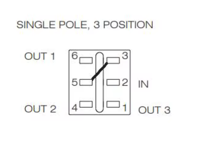
I’m trying to wrap my head around this SP3T switch behavior. The datasheet for this (and other) SP3T switches shows the input pin is #2 with the outputs on #1, 4, and 6.
Yes my footprint numbering is different. Here’s a snipper from the PCB, looking at it from the bottom. It appears to be a mirror image from what you show me here. Which data sheet is this from? The switches I have here are labeled Salecom T80-T. Perhaps their working is mirrored wrt yours..
God this is annoying, sorry about that. When I made this, I thought about what happens if the switch is rotated 180 degrees (nothing), but I hadn’t thought about mirror images