Orange lines are copper traces, large circles are pot-knobs.
I’m not 100% set on the font, don’t feel like it matches the pattern. And I don’t know if bottom symbol looks like a bee? Any critique appreciated, the harsher the better.
It’s good, especially the three dimensionality in the pattern at the bottom. The font has a hexagonal styling that works well with the theme, though the proportions of the individual letters seem a bit off. For example the F vs. O and O vs. D in “fold”. I appreciate what you did with LFO, but it throws off the balance of the design.
Yes it’s a bee, no problem, but it is “hidden” in/ “overwelmed” by the the hive.
Make the bee in white (or whatever silkscreen color you’ll choose), it will stand out better.
This is very beautiful. I would probably be happy with that but without any words. Yes, it’s my ongoing campaign to promote the use of pictograms in modular synthesis. I wonder why emoji are so popular in text but never seem to turn up on control panels where you’d think they’d fit in better.
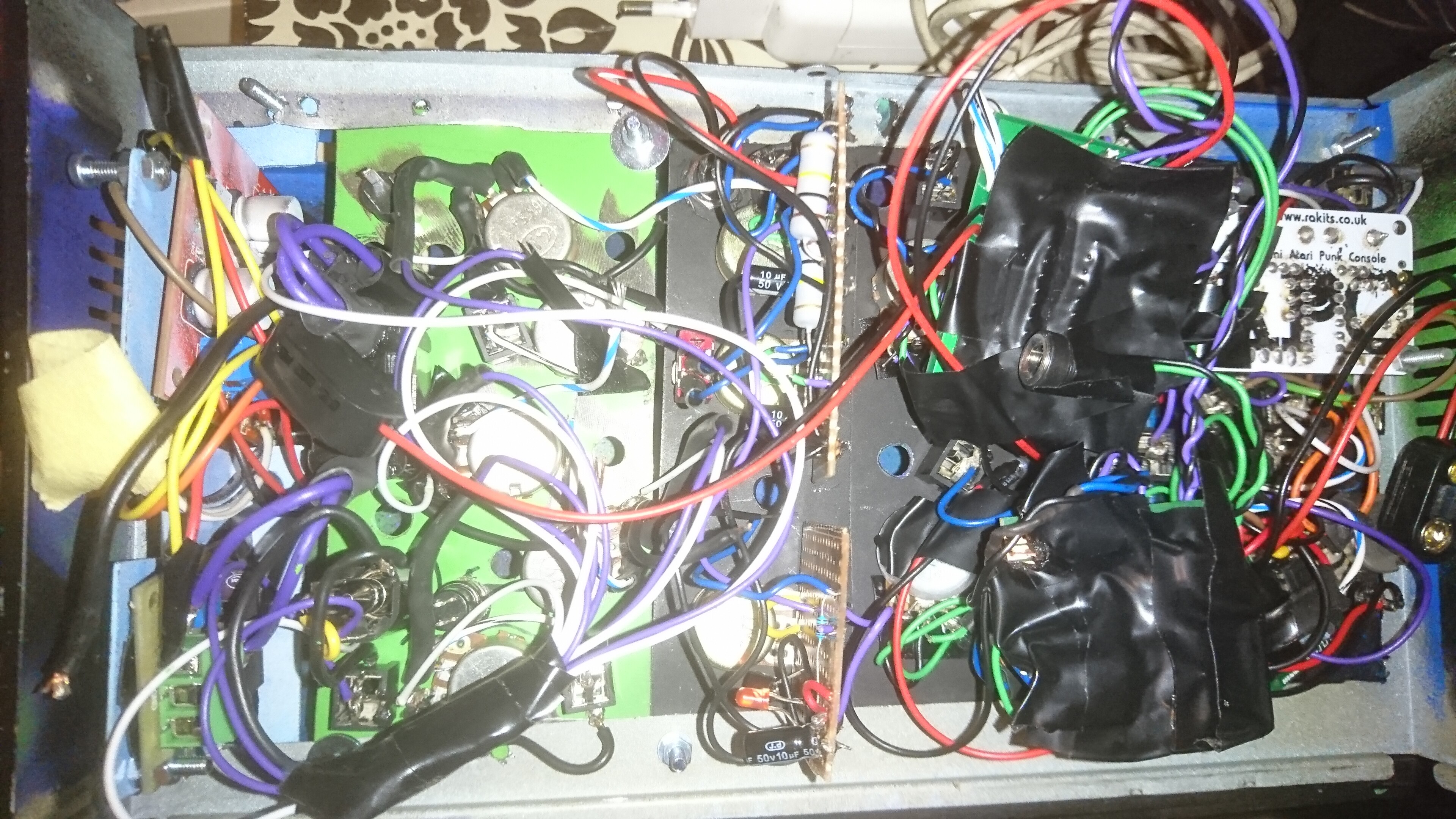
This is the 9volt Tuner Jumpskiff. It does not have a tuner in it, because it was too tall to fit in the front as I had planned so there is no tuner in it, but it was made out of an old TV-tuner. I looked up the size of eurorack panels online, so I decided to do the panels by eye apearently. They are cut from 0.9mm sheets of steel with an anglegrinder, drilled some holes using a drill. They are just about rigid enough for the jacks. The module on the far right got a welded plate in so I could mount a standidng PCB that was too tall, it is the 1$ reverb from ebay. The VU draws to much power that I bother using it, but it was hooked up at one pont. I use those nice paper things that Thonk uses to wrap stuff with so it does not break in the mail, and just spray paint over it, and smear on some random stuff with a marker. Notice how the Rakit APC is bolted on the faceplate, as it had the plastic pots.
This is an APC made by SPAD_ELECTRONICS or something like that, it is a nice kit on ebay, and I think it sounds pretty good. His PCB silkscreens looks awesome. I made the faceplate in the same way, but since I had boght some other modules I was able to make a faceplate that will atleast fit in a eurorack case, as I just took the real faceplate and drew a line around it and cut it slighty smaller. At this point I had even gotten a nice step-bor or what it is called, so the holes are actually round.
When using metal stuff, evrything shorts all the time. I put stuff in those antistatic bags that components come in, and use plenty of electrical tape on the pots. I have shorted one of my PSUs 4-5 times, but after I started putting things in bags and taping them alot I have not had so much problems with that.
I may be in a minority but in most cases I like to see words on my panels. For the waveform outputs on a VCO the pictograms are good, but I find “PWM” and “FOLD” much less bewildering than the pictograms you replaced them with. I don’t know what the squggles on the upper left mean.
And then there are some holes such as upper center and upper right that seem to have no label. There are four holes across the upper middle that seem to have three labels (SYN, CV, FM) associated with them, a mismatch. Are both the middle ones supposed to be CV?
I guess the yellow chevrons are supposed to indicate some kind of path? Those might be better in white, otherwise they just look like part of the artwork.
I like the artwork but I think it risks obscuring the labeling, and I favor much more clear indications of what each control and jack is for.
In my opinion the words are redundant once you’ve learned to use the module. We have whole road sign systems that work just fine without words, and a similar principle applies here.
It’s beautiful! It’s your panel and unless you have commercial considerations then you take or ignore all the advice here. Your unique (world unique) design is yours forever. Sign it. Frame it. Populate and play it. Well done.
I try to use shrinktubes, and after I got a big box of them I have calmed down on the entusiastic use of electricaltape. There are a few places where it is the only way to go, like on the pots or covering up PCBs that are facing metal surfaces. Now I tend to cover the entire cases with antistatic bags instead, but it sure needs some tape to stay in place. The problem with tape in general is that most types tend to have glue problems over time, where it dries out, falls of the tape itself and becomes some nasy gunky stuff or just fuses with the material it is taped to, so it have to be scraped off in pieces. That particular build is not ment to be everlasting for sevral reasons, but it was a superfun project that really got me hooked on synths. I actually think that it will see alot more use once I get a few more baby8 sequencers up and running as the 3 APCs does not tune to volt per octave as moast of my other stuff. Spent about 10 times as much time fixing it as playing it, as my soldering skills have gotten better it does not fail as much anymoar, but because the way evrything is hanging in wires and flopping about it have its own way of falling apart alot.
I’m on my who knows what iteration now. Decided to redo the control PCB layout.
Most of the inputs and outputs are on the bottom now, so it is easier to get to knobs and switches.
^ a circuit you connect to dead circuits and trigger with a piezo - the dead circuits act as a resistor - it is basically an oscillator with an unconnected section - and that section is jumped with your probes and a dead board
But the art… lol. Cornfield.
The circuit is called Blackground Corn.