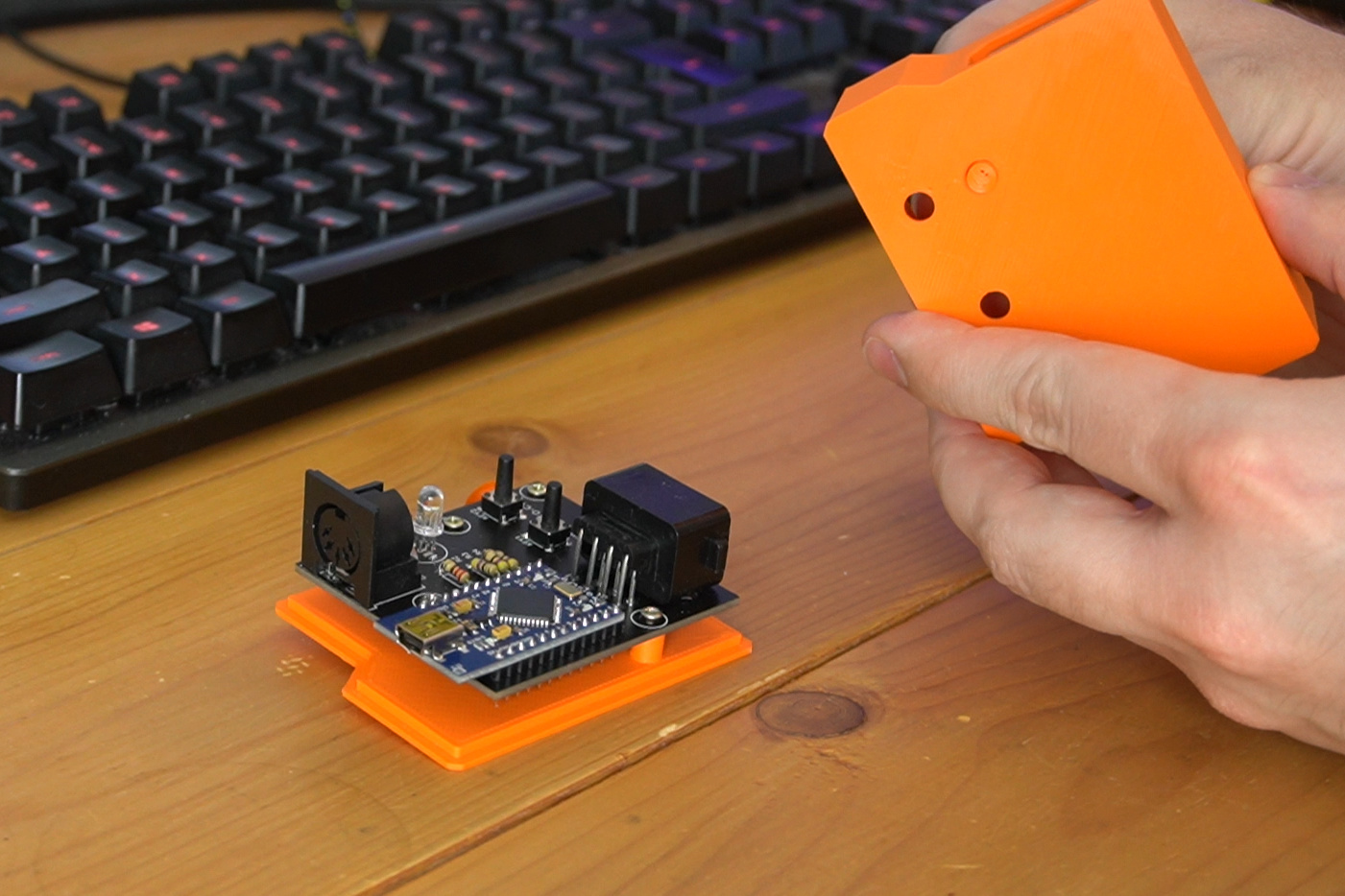
Just a peek at something im working on.


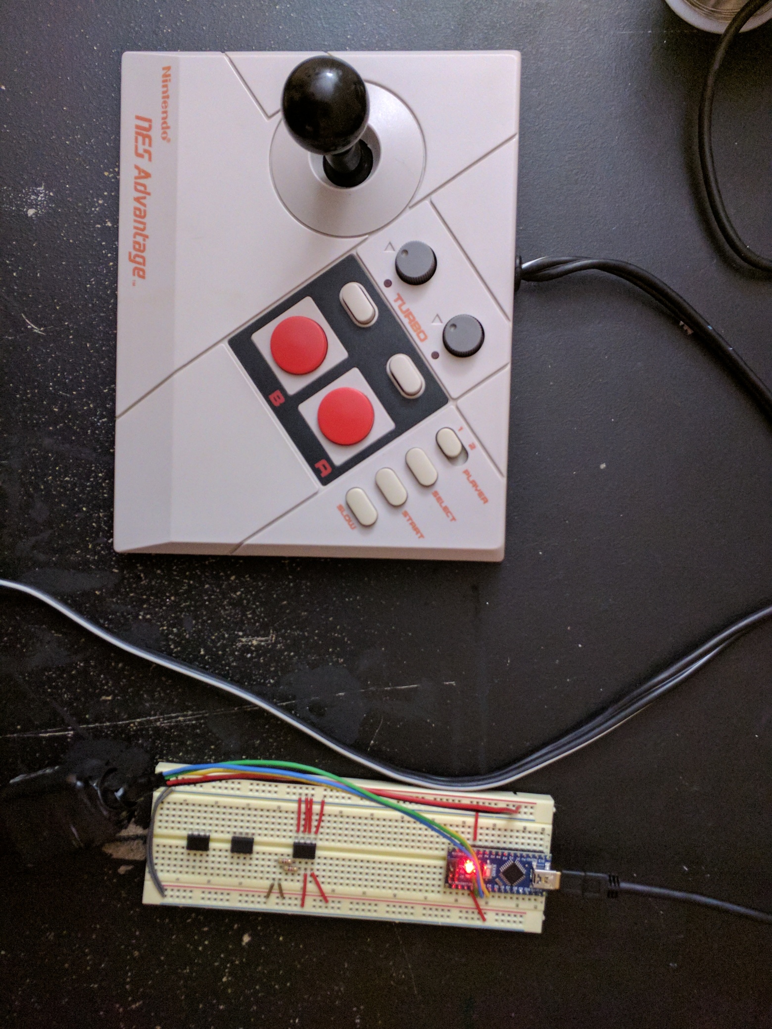
I was all ready to code the arduino to send bits to the 4021 8-bit shift register on this thing, but i guess nintendo controllers are such a popular thing to hack that looks like theres plenty of wheels so i dont have to re-create them.
Credit: Joseph Corleto for the base code
https://www.digikey.com/en/maker/projects/make-an-nes-controller-interface-for-arduino-uno/6d21560a571b490caa2642e87852dacb
I have made some minor adjustments to this wonderfully documented code. I will paste it here for reference:
/*
  ================================================================================

    File........... NES Controller Test Code
    Purpose........ To demonstrate how to interface to an NES controller
    Author......... Joseph Corleto
    E-mail......... corleto.joseph @ gmail.com
    Started........ 04/13/2016
    Finished....... 04/14/2016
    Updated........ --/--/----

  ================================================================================
   Notes
  ================================================================================
  - The NES controller contains one 8-bit 4021 shift register inside.

  - This register takes parallel inputs and converts them into a serial output.

  - This code first latches the data and then shifts in the first bit on the data line.
  Then it clocks and shifts in on the data line until all bits are received.

  - What is debugged are the button states of the NES controller.

  - A logical "1" means the button is not pressed. A logical "0" means the button is
  pressed.

  - This code shifts the first bit of data into the LSB.

  - The order of shifting for the buttons is shown in the table below:

        Bit# | Button
        --------------
          0  |   A
        --------------
          1  |   B
        --------------
          2  | Select
        --------------
                      3  | Start
        --------------
          4  |   Up
        --------------
          5  |  Down
        --------------
          6  |  Left
        --------------
          7  | Right
        --------------

  - The NES controller pinout is shown below (looking into controllers
  connector end):
    __________
   /      |
  /       O 1 | 1 - Ground
        |           | 2 - Clock
  | 7 O   O 2 |   3 - Latch
  |           | 4 - Data Out
  | 6 O   O 3 | 5 - No Connection
  |           |   6 - No Connection
  | 5 O   O 4 |   7 -  5V
  |___________|

  - Please visit http://www.allaboutcircuits.com to search for complete article!

  ================================================================================
  Updates
  ================================================================================
*/
//================================================================================
// Caustic
//===============================================================================
// Just added some outputs for control voltage on pins 5-12.
// at the beginning of the loop, will check state again and bring low if button not pressed.


//===============================================================================
//  Header Files
//===============================================================================

//===============================================================================
//  Constants
//===============================================================================
// Here we have a bunch of constants that will become clearer when we look at the
// readNesController() function. Basically, we will use these contents to clear
// a bit. These are chosen according to the table above.
const int A_BUTTON         = 0;
const int B_BUTTON         = 1;
const int SELECT_BUTTON    = 2;
const int START_BUTTON     = 3;
const int UP_BUTTON        = 4;
const int DOWN_BUTTON      = 5;
const int LEFT_BUTTON      = 6;
const int RIGHT_BUTTON     = 7;

//===============================================================================
//  Variables
//===============================================================================
byte nesRegister  = 0;    // We will use this to hold current button states

//===============================================================================
//  Pin Declarations
//===============================================================================
//Inputs:
int nesData       = 4;    // The data pin for the NES controller

//Outputs:
int nesClock      = 2;    // The clock pin for the NES controller
int nesLatch      = 3;    // The latch pin for the NES controller

// CV Outputs
int OUT1 = 5;
int OUT2 = 6;
int OUT3 = 7;
int OUT4 = 8;
int OUT5 = 9;
int OUT6 = 10;
int OUT7 = 11;
int OUT8 = 12;

//===============================================================================
//  Initialization
//===============================================================================
void setup()
{
  // Initialize serial port speed for the serial terminal
  Serial.begin(9600);
  //Serial.begin(2000000);

  // Set appropriate pins to inputs
  pinMode(nesData, INPUT);

  // Set appropriate pins to outputs
  pinMode(nesClock, OUTPUT);
  pinMode(nesLatch, OUTPUT);

  // Set the pin mode of the outputs
  pinMode(OUT1, OUTPUT);
  pinMode(OUT2, OUTPUT);
  pinMode(OUT3, OUTPUT);
  pinMode(OUT4, OUTPUT);
  pinMode(OUT5, OUTPUT);
  pinMode(OUT6, OUTPUT);
  pinMode(OUT7, OUTPUT);
  pinMode(OUT8, OUTPUT);

  // Set initial states
  digitalWrite(nesClock, LOW);
  digitalWrite(nesLatch, LOW);

  digitalWrite(OUT1, LOW);
  digitalWrite(OUT2, LOW);
  digitalWrite(OUT3, LOW);
  digitalWrite(OUT4, LOW);
  digitalWrite(OUT5, LOW);
  digitalWrite(OUT6, LOW);
  digitalWrite(OUT7, LOW);
  digitalWrite(OUT8, LOW);
}

//===============================================================================
//  Main
//===============================================================================
void loop()
{
  // Will bring the voltage low if button is no longer pressed.
  if (bitRead(nesRegister, A_BUTTON) == 1)
    digitalWrite(OUT1, LOW);

  if (bitRead(nesRegister, B_BUTTON) == 1)
    digitalWrite(OUT2, LOW);

  if (bitRead(nesRegister, START_BUTTON) == 1)
    digitalWrite(OUT3, LOW);

  if (bitRead(nesRegister, SELECT_BUTTON) == 1)
    digitalWrite(OUT4, LOW);

  if (bitRead(nesRegister, UP_BUTTON) == 1)
    digitalWrite(OUT5, LOW);

  if (bitRead(nesRegister, DOWN_BUTTON) == 1)
    digitalWrite(OUT6, LOW);

  if (bitRead(nesRegister, LEFT_BUTTON) == 1)
    digitalWrite(OUT7, LOW);

  if (bitRead(nesRegister, RIGHT_BUTTON) == 1)
    digitalWrite(OUT8, LOW);


  // This function call will return the states of all NES controller's register
  // in a nice 8 bit variable format. Remember to refer to the table and
  // constants above for which button maps where!
  nesRegister = readNesController();

  // Slight delay before we debug what was pressed so we don't spam the
  // serial monitor.
  //delay(8);

  // To give you an idea on how to use this data to control things for your
  // next project, look through the serial terminal code below. Basically,
  // just choose a bit to look at and decide what to do whether HIGH (not pushed)
  // or LOW (pushed). What is nice about this test code is that we mapped all
  // of the bits to the actual button name so no useless memorizing!
  if (bitRead(nesRegister, A_BUTTON) == 0)
    digitalWrite(OUT1, HIGH);

  if (bitRead(nesRegister, B_BUTTON) == 0)
    digitalWrite(OUT2, HIGH);

  if (bitRead(nesRegister, START_BUTTON) == 0)
    digitalWrite(OUT3, HIGH);

  if (bitRead(nesRegister, SELECT_BUTTON) == 0)
    digitalWrite(OUT4, HIGH);

  if (bitRead(nesRegister, UP_BUTTON) == 0)
    digitalWrite(OUT5, HIGH);

  if (bitRead(nesRegister, DOWN_BUTTON) == 0)
    digitalWrite(OUT6, HIGH);

  if (bitRead(nesRegister, LEFT_BUTTON) == 0)
    digitalWrite(OUT7, HIGH);

  if (bitRead(nesRegister, RIGHT_BUTTON) == 0)
    digitalWrite(OUT8, HIGH);
}

//===============================================================================
//  Functions
//===============================================================================
///////////////////////
// readNesController //
///////////////////////
byte readNesController()
{
  // Pre-load a variable with all 1's which assumes all buttons are not
  // pressed. But while we cycle through the bits, if we detect a LOW, which is
  // a 0, we clear that bit. In the end, we find all the buttons states at once.
  int tempData = 255;

  // Quickly pulse the nesLatch pin so that the register grab what it see on
  // its parallel data pins.
  digitalWrite(nesLatch, HIGH);
  digitalWrite(nesLatch, LOW);

  // Upon latching, the first bit is available to look at, which is the state
  // of the A button. We see if it is low, and if it is, we clear out variable's
  // first bit to indicate this is so.
  if (digitalRead(nesData) == LOW)
    bitClear(tempData, A_BUTTON);

  // Clock the next bit which is the B button and determine its state just like
  // we did above.
  digitalWrite(nesClock, HIGH);
  digitalWrite(nesClock, LOW);
  if (digitalRead(nesData) == LOW)
    bitClear(tempData, B_BUTTON);

  // Now do this for the rest of them!

  // Select button
  digitalWrite(nesClock, HIGH);
  digitalWrite(nesClock, LOW);
  if (digitalRead(nesData) == LOW)
    bitClear(tempData, SELECT_BUTTON);

  // Start button
  digitalWrite(nesClock, HIGH);
  digitalWrite(nesClock, LOW);
  if (digitalRead(nesData) == LOW)
    bitClear(tempData, START_BUTTON);

  // Up button
  digitalWrite(nesClock, HIGH);
  digitalWrite(nesClock, LOW);
  if (digitalRead(nesData) == LOW)
    bitClear(tempData, UP_BUTTON);

  // Down button
  digitalWrite(nesClock, HIGH);
  digitalWrite(nesClock, LOW);
  if (digitalRead(nesData) == LOW)
    bitClear(tempData, DOWN_BUTTON);

  // Left button
  digitalWrite(nesClock, HIGH);
  digitalWrite(nesClock, LOW);
  if (digitalRead(nesData) == LOW)
    bitClear(tempData, LEFT_BUTTON);

  // Right button
  digitalWrite(nesClock, HIGH);
  digitalWrite(nesClock, LOW);
  if (digitalRead(nesData) == LOW)
    bitClear(tempData, RIGHT_BUTTON);

  // After all of this, we now have our variable all bundled up
  // with all of the NES button states.*/
  return tempData;
} hell yes!
 never found a clean controller lol!