Im wondering which resistors (around opamp or LM13700) to change in order to get zero resonance when resonance potentiometer is fully closed (ccw). It now shows a little spike as if resonance is dailed in a tiny bit. Any advice highly appreciated.

How have you set R47 ? This looks like it’s a trimmer to adjust the resonance level? Usually you would be focused on making sure the self oscillation is not too extreme. Otherwise you could try reducing R52.
R48 and R52 have values so close to 50k that together with R47 they must be meant to divide the 24 V range in 3 parts. -12V to -6V, -6V to 6V and 6V to 12V. The pot R47 will allow to set a voltage between -6V and 6V. But 49.9 k is a resistor that is hard to come by and if you use 51k or 47k you will achieve almost the same result. And those resistors are more easily available. My 2 cents.
Especially since pots typically have tolerance ±20%, which easily nullifies any difference between 49.9k and 47k.
Thanks for confirming my initial suspicions that those resistor values are weirdly spec’d.
Hi all, thanks all for your replies. Ive changed R52 for a 50k trimmer and no matter how i set it, the reso peak is still there. Let me first upload some pictures ive taken, and to completion also sheet 1 of the MFOS filter. There is no explicit explanation regarding trimming the amount of resonance but. I see comments that the BP is feedback into opamp that feeds the resonance. I’m still unsure which resistors to change. I can ofcourse take a wild guess. 150k resistors over pin 1 (output pin) and the inverting input?? Well. Hope this helps you to help me trimming down this peak of reso. Again thanks in advance.


4 Likes
Hi Jos. Thanks for your reply. Ive tried replacing them both but indeed with the same results. Uhm, where to look next in order to get zero resonance when the pot is fully ccw? Thanks in advance for your advice
Try changing R54 to a 43K or 47k resistor, that should force IABC of U6-A to a lower value and further reduce the feedback/resonance when R47 is at minimum.
EDIT: My reasoning, assuming XRES is left unconnected (more on that later).
With R54=54k, the voltage at the non-inverting input of U5-B is 30/130x-12V=-2.8V
When R47 is at minimum, the inverting input of U5-A is at -6V and its output is (0 - -6)x120/100 = +7.2V
The output of U5-B is then (-2.8 - 7.2)x100/100= -10V
I’m not completely sure how to compute IABC, but I would estimate it at approximately 60µA which is low but maybe not enough to completely kill the resonance.
Changing R54 to 43k, would set the non-inverting input of U5-B to 43/143x-12V=-3.6 and then the output of U5-B would theoretically go to -10.8V, reducing IABC a bit.
With R54 at 47k, U5-output would theoreticaly go to -11V further reducing IABC.
I say theoretically because even with the original value of R54=30K, the output of U5-B is already pretty close to its limit, as it typically doesn’t get less than 1.5V away from its power rails.
So changing R54 might get its output closer to -12V, but it’ll never get there and there will always be a non-zero IABC and thus some resonance.
If the filter was designed by ear rather than with an oscilloscope, it is possible that what the author meant by “no resonance” was actually what you are seeing on your scope.
Can you actually hear that level of resonance? (It does look strong enough to be heard.)
Another point to notice is that the filter is probably not meant to have “no resonance” when the XRES input is not connected, it is only when XRES sees -5V that the filter is meant to provide no resonance. The voltage at XRES is summed with the voltage provided by R47. So R47 is probably more meant as an adjustment to the maximum resonance rather than the minimum. To barely keep the filter from oscillating at maximum resonance.
If you really want zero resonance, you might have to replace U5 by a Rail-toRail opamp.
3 Likes
Hi Antoine. Wow! What a great explanation and thanks for the effort. I really appreciate it. As soon as I get home, I’ll try I’ll changing R54 and let you know the results.
I have another VCF (Moritz Klein) based on two vactrols and when I turn down the resonance knob, the resonance is completely off as it should be imho. I like to get a clean square wave if the resonance is turned down, but since the MFOS filter is another design with another components which behaves differently, I can imagine that this could happen. It is not a very big problem, but its just my autistic mind that says, if no resonance is dailed in, no resonance should be visible or audible ![]()
anyways, again many thanks and have a nice day
1 Like
R48 and R52 are part of a voltage divider, so the little that I know tells me that changing them alone should make no real difference. I think that @antoine.pasde2 might be on to something with the rail to rail op amp suggestion. Assuming that you only need the op amp to swing down to the negative rail, you might be able to use the lowly and cheap LM358. Might worth the try as this is a 10c common part.
1 Like
I have to mention here your feat of fitting this VCF on a 14x34 piece of stripboard, including the standoffs. That’s a hell of an elegant layout!
2 Likes
Hi K. Ostas. Thanks. Yeah i try to make it as tiny as possible leaving just enough space to make repairs if nessesary. Panel is 20cm long and the width depends on how many pots and jacks.
Hi, i promised i will inform you when i tested your advice by replacing R54 (33k) into 47k. Well the results are: same resonance spike when reso knob is fully ccw. Unfortunately this didn’t solve it. Instead when fully open up resonance, its not self oscillating anymore (slight whistle only as if self osc is just about to kick in). I really dont need self oscillating (i think) please advice why i should wanna have it. So it looks like R54 is limiting the upper resonance region. I try to find the lower region. If you can advice me what to look for next i would be very greatfull.
Some use cases for self oscillating are:
- Using the filter as an extra sine wave oscillator. E.g. as sub octave, or as an audio frequency modulator for FM or ring modulation, etc. Anywhere a sine wave oscillator makes sense, really.
- For accent in a sound. If, for example, the resonance level is controlled by an envelope generator or an LFO, you can get self-oscillation just for a fraction of a second, potentially completely transforming the sound.
If you still want to be able to completely eliminate the resonance, apart from replacing the opamp by a rail-to-rail one, you could try bleeding off some of the IABC current by adding a resistor from pin 1 on U6-A to the -12V negative supply. Maybe start with a 47k.
It’ll slightly limit the maximum resonance too, but that effect is probably negligible as the voltage at pin 1 of U6-A doesn’t rise much more than 1.2V above the negative rail so the maximum current stolen by this additional resistor would be limited to 1.2V/47k = 26uA
Here is a simple simulation on https://www.falstad.com/circuit/
where I replace the opamp and everything upstream of it by a voltage source going from -10.8V to +10.8V, the approximate maximum range of the opamp.
https://tinyurl.com/25zce6xo
Here’s a screenshot of the simulation, if you don’t want to follow an unknown link (as you shouldn’t).
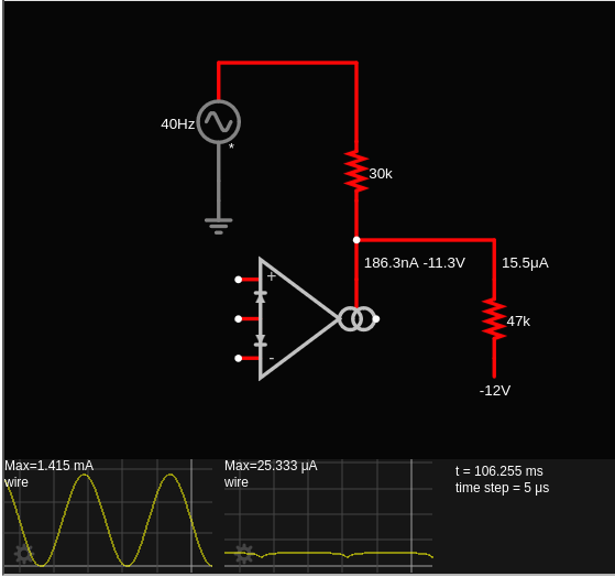
The sinewave at the bottom is IABC, the flatish line to its right is the current through the 47k resistor.
2 Likes
Thanks again for your help and explanations. I’ll dive in asap and learn something from it. ![]()
I’ll let you know the results when connecting the 47k resistor to pin 1.
Since im working with opamps the last 4 years, i thought same results could be achieved by just changing resistor value from output pin to inverting input pin of an opamp to get higher or lower current values that feeds the resonance thingy. Apperantly changing resonance with lm13700 chip needs different approach.
Hi Antoine. I’ve just tested it by putting a 47k resistor between pin 1 (lm13700) and -12v. Absolutely nothing changes. Not on the scope, no audible changes, nothing. I even have changed both 33k resistors connected to the cutoff potentiometer. Also no changes there. With and without, tried other values, nothing. Starting to wonder why these components are even there ![]()
Still, i would really like to have a clean square wave having zero reso when i need it.
The amount of reso at the moment is to noticeable.
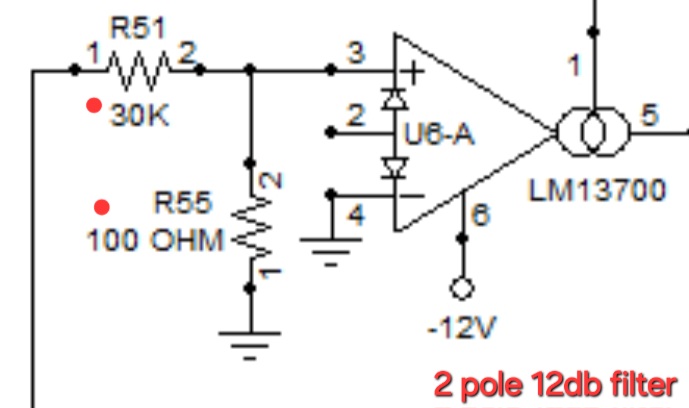
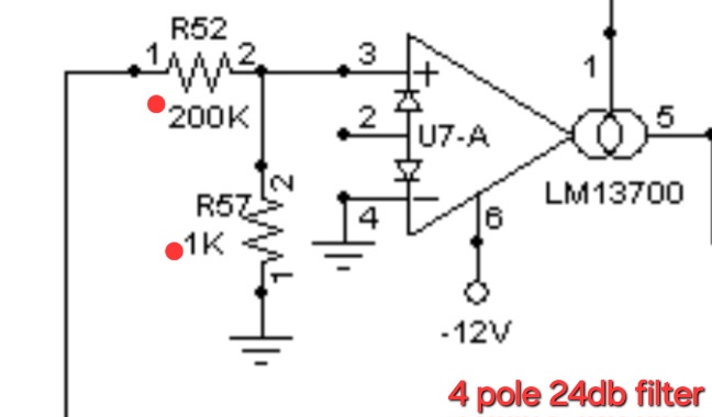
I looked up the other mfos filter, the 4 pole 24db one and compared both schematics. I do see little differences there but not sure if i could implement them. Its the resistor pairs on pin 3 of the lm13700.
What are your thoughts about that?
2 pole 12db
4 pole 24db
OK, that’s weird, it should have made at least some difference, unless my estimate of the voltage out of U5-B is significantly off.
What voltage do you measure at pin 1 of U5-B when set for minimal resonance?
How high does it go at the maximum resonance setting?
You can always try with smaller resistors from U6-A to -12V: 22k, 10k, even 4.7k.
If none of those make any difference, try removing R46 or R22 entirely, if that doesn’t make a difference, I’m chasing the wrong issue.
I missed this comment earlier. You can definitely control the amount of resonance by adjusting some resistor values. But that is either static or controlled manually with a potentiometer. What the use of an OTA such as the LM13700 allows, is voltage control of the amount of resonance through the XRES input.
R1 and R5 have nothing to do with the amount of resonance (at least not directly), they determine the maximum and minimum initial cutoff frequency, measuring the cutoff frequency is not easy unless the filter goes into self oscillation, at which point the cutoff frequency should control the oscillation frequency. (Another use for self resonance, I guess. ![]() )
)
Gonna measure this tomorrow and let you know.
Anyways, thanks again for your help. Means a lot. I’ve reverted all changed components to their standard settings conform the schematics. I did document the changes i’ve tried. Maybe someone else is having the same issue. Maybe it is supposed to be like this but still. If we could solve this for me it would be an improvement. It self oscillates nicely again and in tune over 5v too so issues there.
I connected the xres input to my cv processor, which i can turn down/up voltages between -10 and +10v. So i fed it with -5v, on my scope the reso spike still the same. Even with -10v
Hi Antoine
Found an article:
The issue of a non-zero resonance when a potentiometer (pot) is fully counter-clockwise (CCW) in an MFOS 2-pole 12dB filter is likely due to the inherent characteristics of the filter design or component tolerances rather than a flaw in the circuit itself. Specifically, even with the resonance control fully attenuated (CCW), some residual resonance or feedback might be present, especially at the filter’s cutoff frequency. This can be caused by the way the filter’s feedback loop is implemented, even with minimal feedback.
Here’s a more detailed explanation:
- Filter Topology:
The MFOS 2-pole 12dB filter likely uses a state-variable filter topology or a similar design. These filters inherently have a feedback loop to achieve the desired resonance and cutoff characteristics.
- Resonance Control:
The potentiometer controlling resonance typically adjusts the amount of feedback in the filter circuit. When fully CCW, the feedback is minimized, but not entirely eliminated.
- Component Tolerances:
Resistors, capacitors, and other components in the filter circuit have tolerances. These slight variations can affect the exact behavior of the filter, especially near the extreme settings of the resonance control.
- Cutoff Frequency Interaction:
At the cutoff frequency of the filter, even a small amount of feedback can cause a noticeable resonance effect.
Therefore, it’s not unusual to observe a small amount of resonance even with the resonance control fully attenuated. If the resonance is significantly louder than expected or if there are other issues, then it would be best to check for any soldering or component issues.