MFOS 2 pole 12db state var. filter

Those article quotes are a bit generic, it almost sounds like an analysis of the circuit generated by an AI that hasn’t actually seen the circuit.

I’ll understand if you’ve had enough of this back and forth, but I would still be curious to know the values of those voltages at pin 1 of U5-B, and the effect of using smaller resistors from U6-A pin 1 to -12V.

R51 and R55 in the first circuit form a voltage divider as do R52 and R57 in the second one, the ratios 300:1 and 200:1 are similarly large, their exact value depend on the amplitude of the signals coming in. Having a bigger ratio would reduce the resonance but only linearly and would affect the maximum resonance as well as the minimum resonance whereas I believe that adding a resistor from U6-A pin 1 to -12V would affect the minimum resonance much more than the maximum resonance.

1 Like

Yes, a little bit but how can i give up? You’re such a great help. Give up on this now would be very disrespectful towards you so no! I would love to try to investigate this further and solve it together. Beers on me​:grin::+1::clinking_beer_mugs:

Since im out of ideas maybe you can look into it and let me know? Thanks a million.

Yes google came up with this. True or not it describes exactly what i have

I try to measure these voltages as soon as i get home today. Im curious too and love to see it solved. This as an improvement of the schematic. Same thing with 43k, 49,9k, 51k resistors. They dont exist in Europe. Its 47k.

When first started this discussion here, @JaggedNZ and @analogoutput where talking about this and answered: Thanks for confirming my initial suspicions that those resistor values are weirdly spec’d.

So maybe there are other improvements to make, but first the resonance.

Are you planning on building this filter too? Besides the resonance thingy, it sounds awesome!

Hi @antoine.pasde2

Here are the voltages as per you request from pin1 of the lm13700 chip (U5-B)

This with all pots turned down especially the reso pot:

And this with reso pot fully on (self oscillation)

20millivolts difference?

This is without an extra resistor tied from pin1 to -12v. Will test that later..

Can you confirm if this is correct?

Thank you for taking the measurements.
That seems OK for pin 1 of the OTA, although I would have expected a slightly larger difference, and confirms that the additional resistor would have very little impact on the maximum resonance, but the voltage I am really interested in is on pin 1 of the TL082 opamp, not the OTA.

The fact that this voltage is so close to -12V also indicates that the additional resistor will have to be relatively small to have any effect, and explains why the 47k had no effect.
4,7k might be a better value to test.

Hi, oops sorry, will send the information of the output opamp asap.:grin::+1:

Here are the results (still without the extra resistor)

With reso pot fully closed (ccw)

And with reso pot fully open (cw)

Big difference but since im bad at mathmatics i have no clue what it means :slight_smile:

Does these values tell you what you wanted to know? Whats the next step to do?

Yes, thank you, this tells me quite a few things. Especially combined with your previous measurements.

  • It confirms that the output of the opamp doesn’t get close enough to the negative rail, so by itself it cannot completely shut down resonance.
  • The OTA’s bias current IABC varies from (-10.73V - 10.95V) / 30k = 7.3uA for minimum resonance to (-4.46V - -10.76V) / 30k = 210uA for maximum resonance.

These are lower numbers that I expected, but even at 7.3uA, the OTA provides some gain.

My simulation indicates that a resistance from pin 1 of the OTA to -12V somewhere in the range of 47k to 4,7k should do the trick by bleeding off most of that 7.3uA.
Maybe start at 10k and go up or down by factors of “2”.
You should use the largest resistor that kills off the resonance so as to not lose the ability to self oscillate.

Ok cool. Gonna try this and come back to you with the results👍

What voltage are you aiming for to get lower reso but still enough to have self-osc??

Hi,

Just tested it now with different resistor values from 4.7k up to 82k.

Funny thing is, as soon as i plug in (yes, i soldered in a female socket between pin 1 ota and -12v), the 47k resistor, the self oscillation (fully open) cuts down half. Every resistor below 47k completely shuts down self oscillation. Every resistor greater then 47k does nothing. When turning down the reso pot fully ccw, the same old reso spike still remains (just like one of the first screenshots from this post). So, maybe we need to take a look somewhere else that causes this? I can swap out opamp and/or lm13700’s just to be sure its not a faulty chip causing this..

This reso is just to much when potentiometer is fully closed imho

Hey Marty, thanks for taking the time to do these experiments and for giving me a detailed report.

Yeah, I’m starting to think that too.
I took a new look at the rest of the circuit, I had so far focused on the resonance feedback circuit.
After chasing a couple of false leads, I don’t see any obvious candidates for the source of the extraneous resonance.

I agree.

One way to make sure that the resonance is not coming from the part of the circuit we have been examining would be to completely remove the U6 LM13700. It is socketed right? The other half of U6 is unused, so removing it would break the path from (RA) to (RB) and should be like completely turning off its contribution to resonance but the rest of the circuit should continue to work.

Other things to look at:

  • double check the value of resistors, in particular R46
  • check for solder bridges or other shorts

By the way, which one of the three outputs, LP, HP or BP are you seeing the resonance bump on?

Its the LP output. I never tested the other ones (stupid me). Good idea. Gonna try that.

Btw, the graph on the scope is LP with the cutoff pot fully open. As you can see absolutely no rounded edges on the waveform. I wished the resonance will just be as clean as the cutoff.
Hopefully we bump into the cullprit.

Ive tried also BP and HP.

Spike on BP looks the same as on LP, but the spike seems higher on the HP which does make sense. Its high pass. I didnt use any 100nf capacitors to the + and - of the IC’s though to eliminate high frequencies.

Pretty sure its clean of flux, debris or other dirt that can cause short circuit.

Will do check that too

I also do see that the BP output U3-B, feeds the resonance? Maybe there can be something to look at

Hi @antoine.pasde2

Guess what? I think we might get closer now to find the issue.

I’ve taken out the LM13700 and the spike still remains haha on the square wave. Good thing is that narrows it down to the opamp. What could cause the opamp to have a spike?

Maybe a stupid question, but why is R44 120k? Since the rest is 100k? What effect does the 120k do to the opamp?

Furthermore i’ve read through the information on the mfos website and my eyes stumbled upon this line: The band pass output is inverted and given a gain of 3 by U3-D which feeds the resonance/feedback circuit (Point RA).

Can we change this gain and see if this influences the spike of the opamp?

Anyways, i like to thank you for all the help so far. Hope we can stay in touch and try to find the last piece of the puzzle to solve this

With U6 removed, the opamps in U5 are also essentially out of the circuit as their outputs go to the removed U6 and have no way to reach the rest of the circuit to affect it.

With U6 removed, the output of U3-B goes nowhere through U3-D, so the source of the remaining resonance must be elsewhere.

Feeding back the BP output to the input of the circuit is a standard part of a state variable filter design.
I was not very familiar with state variable filters, but I found this video that explains them quite well.
https://www.youtube.com/watch?v=esKrrjFJyuk

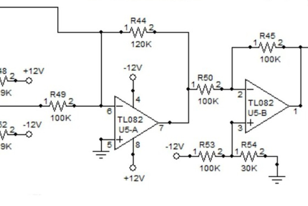
As for why R44 is 120k instead of 100k, that just gives a bit more gain on the XRES input. I’m not sure why that was deemed necessary.

At this point, I am pretty much out of ideas, I won’t claim to fully understand the main part of the filter.

The output of U4-B (which is essentially the BP output before it is buffered by U3-B), seems to be fed back to the input of U2-B through R23 at the same point that RB, the output of the resonance control circuit, is also fed back.
So it seems like that could be the source of the remaining resonance when U6 is removed, but it could also just be part of the negative feedback loop around U2-B, since that part of the circuit is identical to the circuit formed by U4-A and R24 in the negative feedback loop of U2-A.

I’ll let you know if I come up with other ideas, but I wouldn’t be surprised if that resonance is an unavoidable “feature”, an integral part of a state variable filter which, by design, relies on feedback of both the LP and BP outputs to the input.

If you really want to try something, you can see what effect changing R23 has.
Actually I’d be tempted to remove it entirely to see if the BP fed back through the resonance control circuit is sufficient to keep the state variable filter functioning normally.
But don’t feel you have to do that on my behalf, it seems like it could be a difficult task with risks of damaging the circuit.

Hi Antoine, i can imagine that you run out of ideas. Still im very thankfull that you have looked into this. I really appreciate all the efforts. Thanks mate.

Im gonna test few resistors and if the spike is not going away, i think i leave it as it is.

Ok, interessting. Gonna take a look at

On my to do list👍

Just checking this to be sure:

The limiting resistors (7,5k) between transistors Q3 and Q4 to pins 1 and 16 of the OTA. I used 10k here instead. I assume this is not causing this unwanted reso on the opamps output?

Maybe if @analogoutput is up for this to shed some light on it from his perspective would be very helpfull. :grin::+1: