I’ve been eyeing this one @juggle! I would have to order the transistors though. And a piece of stripboard big enough for it.
It works with the BC’s as well you just have to flip them the other way. I used the 2N2904’s because I have a ton of them (got a box of like 200 for $5 or something equally cheap.)
The original design actually uses BC’s I just breadboarded up enough to test that it worked with 2904’s as well before building my version.
It does take a rather large piece of stripboard though - fullsize “Large” from Tayda. I was more worried about making the I/O well organized than making it as compact as possible.
3 Likes
If all you need is CLOCK/2 and CLOCK/4, Carmello Azzarello’s sub oscillator (revised version) does those as a bonus feature.
And in principle you could replicate the main part of the circuit to get CLOCK/8 and CLOCK/16, or even just build two and run the CLOCK/4 output from one into the input of the other.
4 Likes
Is there any difference between a sub-osc and a clock divider other than intended use?
2 Likes
Pretty much DC versus AC coupled outputs.
2 Likes
THAT is really really cool !! I’ve wanted to build the Fonik Rönnberg Divider for a long time, so I have everything for it. And now you come around the corner and share this wonderful layout, very, very cool !! I think that this should definitely be posted in the “Veryfied Stripboard Layouts” thread!
@analogoutput That’s right, he doesn’t really do anything else. I haven’t even thought about that yet. Good idea. I’ve built the sub oscillator a couple of times, it’s very easy to build.
2 Likes
I need to learn how to cross-post 
I like to use my own thread as a sort of blog…but then feel guilty spamming the same stuff into other threads…but I know not everyone is interested in reading my long winded blogish build thread.
I actually thought I had posted it there as well though…but now I see I just shared my version of the noise drum there.
If you do use my layout and confirm it I’ll feel better about posting it - since I did have the one mistake I found initially and I’m still having that issue with /8 being flaky.
I’m actually kind of thinking about doing a PCB version of it for practice…but I’d rather build something I haven’t built already right now
2 Likes
Cross what?!? 
It will be a while before I build it, but it’s definitely in the top three on my list! I’ll let you know as soon as I’ve built it. If you have more stripboard layouts (they don’t have to be your own, the main thing is that they work  ), I would be happy if you could share them with me. I’m always looking for things that I can build, I’m still missing a lot of things.
Greetings Thomas
3 Likes
I’ve been putting everything in a git as I go, a separate folder for each module:
Haven’t pushed anything in a few weeks since I’ve been focused on getting my sequencer connected to the synth and getting this DIY PCB etched and working…but will probably push the PCB soon - just want to try and contact the person who did the schematic to make sure they don’t mind me sharing the PCB I designed for their circuit.
3 Likes
I love a longwinded blogish build thread. Especially one that later develops into say a @juggle wiki “How I dun it!”
The only time to stop is when people… sorry? What? Waffle! Ah ok. Signing off.
1 Like
Finally getting around to putting this together.
Is a NTE159-5 a suitable replacement for the 2n2904? Oddly enough, the only datasheet I can find for the 2n2904 is for the PNP version that I also have a million of.
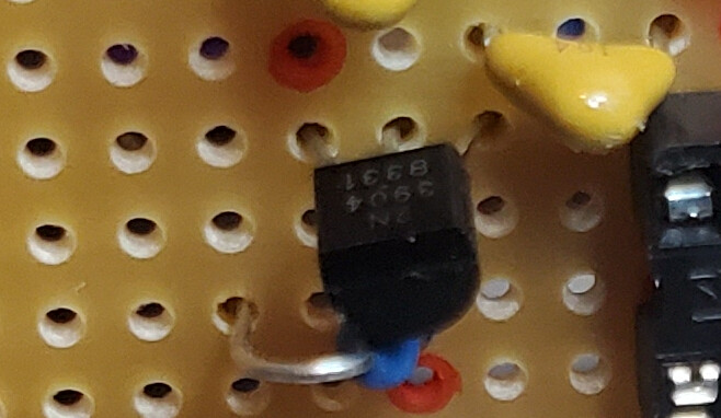
Pretty sure that’s a typo, supposed to be 2N3904. From @juggle’s photo:
NTE159-5 is PNP so no, don’t use that.
5 Likes
Good catch, I’m horrible with numbers and get them mixed up all the time. I’ll try and correct that tonight.
it is indeed supposed to be a 2N3904
Whelp, good opportunity to pull the trigger on my mouser & tayda orders!
1 Like
Does anyone know if Rönnbergs Stripboard design has the signal on the rising edge or the falling edge?
See this thread for more info on this…
https://modwiggler.com/forum/viewtopic.php?t=229782
Rönnberg writes:
It’s original design was made by Mathias Herrmann for his inspiring Fonitronik. However, his design gives inverted outputs, which I changed to normalized outputs.
The clock input is inverted before being applied to the 4024, so transitions happen on the rising edge.
2 Likes
4 Likes
hello, I have a problem here, I am a beginner, I built a clock divider, but after connecting it, it lights up 1/64 and otherwise it does not respond, I would like to ask if anyone has encountered this, thank you
[image]
Can you post a picture of your work? How about the schematic? I’m new at this too and I’ve had a lot of help from this forum, specifically about a clock divider. More details about it’s behavior may be helpful. So far I gather the 1/64 output indicator lights up and this is all the activity. It this correct?
1 Like