That “vRef” is just a simulated ground in order to run the circuit on a single power supply. Most modules use bipolar supply so don’t need such a thing.
It’s not really a voltage reference, just a voltage divider between the +12 V rail and ground.
I made a similar simple LFO and I had this issue. The problem in my case was that i didnt clean the pcb well with alcochol and there was kind of a short circuit, which was dragging the psu. It was small enough that it didnt affect the other modules, but the vcos, because they are also simple ones, depend on the psu to be strong. When I dissasenbled the LFO unit, I could see where the leakidge was, because it created a whiteening where the short was.
So I reccomend cleaning your pcb well with alcochol. Use a toothbrush and dont be too gentle. I thing these lfos are oscillating from rail to rail, so if there is a leak, it eats up alot if power.
It happens on every LFOs and on breadboard too, so it’s unlikely.
I noticed having LEDs increase this effect, so i guess it’s some kind of current drops. Pretty sure i have a decent power supply tho…
Yeah, the problem is that these simple VCOs depend on the PSU too much. Try adding capacitors on the LFO and the VCO units then, if you dont have. 100uF for example. I had all kinds of problems if I didnt add capacitors on both rails on every module. Add big ones on the psu itself too - 3000 uF for example. Also it might help to stack capacitors with different values in parallel, to filter oscillations on different frequencies - like 100nF, 1uF, 10uF. And these oscillations are typically above the hearing range so you have to search for them with an osciloscope. Infact, it is reccomended that every CMOS chip should have a 100nF capacitor as close to it as possible. I think your 555 is a cmos. You might have a good PSU, but without capacitors every little current draw will affect the other units, because they are connected first to eachother, and then to the PSU
Yea that’s what i suspected as well, but no matter how much caps i add it doesn’t change anything. All my modules have two 100uf right after the power connector and then 100nfs +15 to gnd /-15v to gnd as close as possible to each chip.
Even if i trust my power supply, i just bought an RT-65C, i hope it fixes that shit.
Yeah, then if you have two psu’s you can just connect the VCOs to one of them and the other modules to the other so that could be a workaround.
You can try just connecting a diode and resistor to the psu, while the vco is playing, to see if the vco is really that succeptible to current draw. You might have a bad soldering somewhere on it. I would also clean the vco with alcochol too
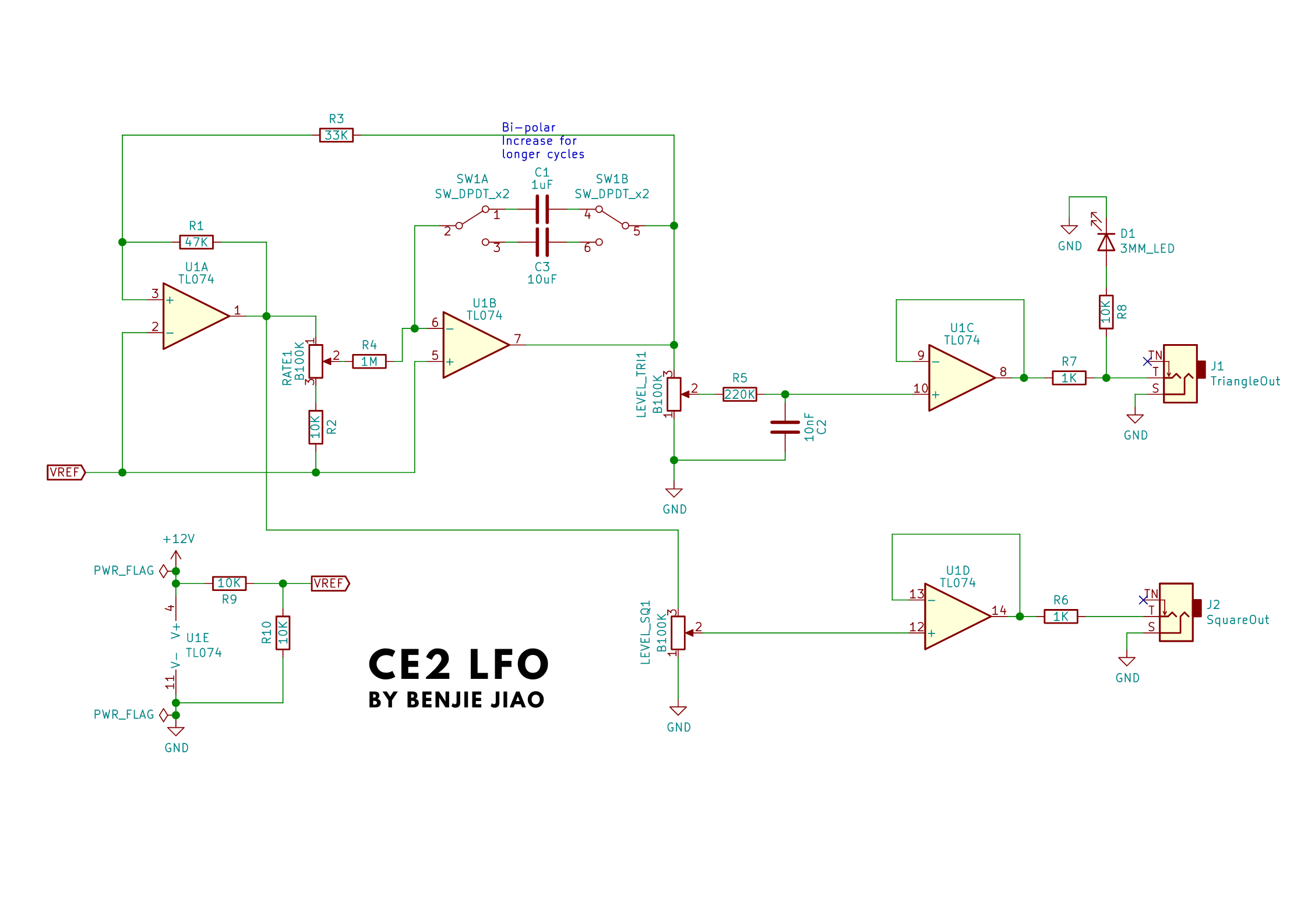
Yea i suspected something like that as well. The only LFO that doesn’t affect my VCOs is the one i posted above, with op-amp connected to a vRef instead of ground. On the same circuit if i add a LED from signal out to gnd, the issue reappears.
That’s what the schematic shows. The only DC connections to ground are via 100k resistors.
Sounds like a smoking gun for the ground issues theory. Check the PSU, LFO, and VCO all have good ground continuity to each other and that all points in the VCO circuit that should be ground have continuity to the PSU ground.
Just received my Meanwell RT-65C, and the problem is almost gone !
It’s still sligthly noticeable if you pay attention tho. So i don’t really know where’s the source of the issue.
So now it’s almost gone i can get rid of this completely by putting bigger resistors for LEDS and slightly reducing their power drops.
Or now i’ve got two PSUs i can just use the other one for LFO based modules only.
If you have typical regular LEDs with typical limiting resistors, maybe 470R or 1k, powered with 12 V, then each will be drawing e.g. (12-2)V/(470 to 1k) ~ 10–20 mA current. Not an overwhelming amount for one LED, but if you have a bunch of LEDs and a marginal power supply it could be a bad combination.
Here’s some discussion of using so-called superbright, or as I prefer to think of them, super low current LEDs; they’ll give decent non-blinding brightness with very much smaller current draw:
For instance, red LEDs with 22k resistors: current ~ (12-2)V/(22k) ~ 0.5 mA.
In the Haillant LFO linked above there’s an LED powered by a (maximum) ±6.3 V triangle wave; with the op amp driver, the current is ~6.3V/(470) ~ 13 mA. The CE2 LFO has an LED powered by a variable amplitude, but presumably no more than ~ 5V, triangle wave, with a 10k resistor and no driver, so that’s around (5-2)V/10k ~ 0.3 mA. The LED seems reasonably bright in the video so probably it’s a superbright, but the description doesn’t say. Anyway, if it’s the LED current that’s the issue, then using those component values, it’s no surprise the CE2 has less effect on the voltage rail then the Haillant.
