Thank you again, I think I have a somewhat okay module now. I will order in a few days and see how it works out! (Then I still need to manage the software part, assuming that the hardware is okay).
I made the panel today:  Pretty happy, just thinking if I need to rename some of the stuff.

8 Likes
I have not yet ordered, too much other stuff happening…
I was wondering however if my bypass will work as I intended:
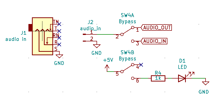

I use one side of the dpdt for the LED and the other connects the audio in jack to
(1) opamps and then ADC, or, if the switch is turned to “off” (2) directly to the audio out jack. Is the output of the DAC still being connected to the output jack a problem? It should be at 0 volt when there is no signal coming in, but does that interfere with the original input?
Even if not, with the output of the DAC still connected when the module is off (bypassed) the stuff (echo/loop) that is currently played will still be played and go into the output… I probably need to rethink my bypass switch! But if I disconnect the output of the DAC as well then I won’t have a “channel” for the LED… 
Usually a bypass is wired this way :

You can obviously add the LED on the second half of the switch…
2 Likes
Oh yes!! Why couldn’t I think of that?! I feel stupid again! XD thank you a lot!
But like this it’s not a “True bypass”, for that you need a DPDT (2x 3 pin)
to deconnect completely input and output .
@fredrik shared this link in another thread
3 Likes
Yes, but with synth levels/impedances, it doesn’t matter if the IN jack stays connected to the electronics…
It’s a whole other thing with guitar levels/impedances…
4 Likes
I made a few stupid mistakes, where I have the inputs of the opamps swapped, but apart from that it seems to be somewhat working as a bitcrusher at least!
One very odd thing though: it only works if I boot the arduino not connected to the PCB (only with the usb cable between laptop and arduino). Then I can insert it into its socket and it works. If I just power on the PCB with arduino inserted (or press reset while its in the socket), it only does the setup() bit and then stops. I am running this example (I have some different pins, which I have adjusted in the audiohacker library).
I think, it’s in line 81
AudioHacker.writeDAC(playbackBuf);
at least, it does not get stuck if I comment that out.
It might be in this spiWrite function, (which is called in writeDAC). There is a while loop which could be running forever, but I have no idea if that is what happens or why that happens and why it’s different if the arduino is on the PCB while it’s booting…
static inline __attribute__((always_inline)) byte spiWrite(byte data) {
  SPDR = data;
  while (!(SPSR & _BV(SPIF)));
  return SPDR;
}
Any ideas? What can I try?
1 Like
I found the solution!!
I have one of the switches connected to D10, which is the SS pin for SPI on the nano. When the switch pulls D10 to ground, the SPI transmission can not work. I have not yet understood why it works when the pin is pulled to ground after a few transmissions (when I insert the board later), but I am happy now. Only need to cut a trace again and use another input for the switch
3 Likes
Okai, the hardware works now, I would say! ![]()
Software also, kind of, but I need some help!
What I did so far, is:
- always record the audio into the SRAM chip (if it’s full, start at address 0 again)
- if I press the button, stop recording and playback from the SRAM chip from current address (that means it starts the playback from the oldest “timestep” it has)
- I can change the sampling rate for recording and playback (I’m using the same for both), which changes the pitch if I do it during the playback and changes the possible length of the recording.
That’s quite cool already, but it’s not yet the effect that I am after! I would like it to be more like the 2hp freez, which Sam used here:

How can I do that? I guess that one is more like a delay, which disconnects the input when you press the button?? so I have to add some kind of feedback from the output into the input and then change the length of the delay??? how?? I don’t really understand what’s going on there xD
Does anybody know how to achieve this kind of effect?
3 Likes
Okay, some progress:
I will write a bit more what I tried tomorrow
5 Likes
With video this time, because I added this shiny LED button 
The logic is like this:
if in record mode (default):
record input to SRAM (circular buffer) and wait for button press
on press: read potentiometer → loopLength. set current address (in buffer) as loop endpoint and currentAddress - loopLength as loop start (I have a bit of logic to cover for buffer wraparound, but not yet fully working), then go into playback mode!
playback mode:
play the buffer from loop start point to loop end point, go to start point again
read potentiometer and use that value to set the playback sample rate (that makes the sound speed up / slow down and change pitch).
If button is released: go back to record mode, set sample rate back to default.
It works okay, but some issues: I can not go to very high pitches/ short repeats, because I can not get the sample rate higher than ~50kHz, if I do, the sound drops out, I think it’s Arduino limitation. How can I get faster playback then? skip samples? combine the sampling rate with skipping for faster? use a lower recording sample rate?
The sample rate used in playback is absolute, so if I press the button the pitch instantly changes, I will set this to relative changes, I think.
I still like the 2hp freez more, but I still don’t really understand which parameters they change with the potentiometers. they also Any ideas what is happening there are welcome! I think they also change the playback sample rate once the button is pressed, because the pitch shifts when you turn the knob while button pressed, but then they also have the separate sample rate knob below… the manual says the upper knob is length/size and the lower one is sample rate. 
Here’s the (very bad and uncleaned) code, if you’re interested:
#include <AudioHacker.h>

#define DEBUG
#define OFF 0
#define PASSTHROUGH 1
#define RECORD 2
#define PLAYBACK 3
#define RECORD_DONE 4

#define PLAY_BUTTON 8 // sebi
#define LED_BUTTON 3 // sebi

unsigned int playbackBuf = 2048;
unsigned int passthroughSampleRate;
unsigned int recordingSampleRate;
unsigned int playbackSampleRate;
unsigned int timer1Start;
volatile unsigned int timer1EndEven;
volatile unsigned int timer1EndOdd;

int currentA0Position;
volatile long address = 0;
volatile long endAddress = 0;
volatile byte addressChipNumber = 0;
volatile byte endAddressChipNumber = 0;

volatile long loopStartAddress = 0;
volatile long loopEndAddress = 0;
volatile boolean looparound = false;


volatile byte mode = RECORD; //SEBI
unsigned long lastDebugPrint = 0;
unsigned int readBuf[2];
unsigned int writeBuf;
boolean evenCycle = true;
unsigned int recordStartTime;
unsigned int recordEndTime;
boolean sampleRecorded = false;

unsigned int bufferLength = MAX_ADDR;

void setup() {
#ifdef DEBUG
  Serial.begin(115200);        // connect to the serial port
#endif

  recordingSampleRate = DEFAULT_RECORDING_SAMPLE_RATE;
  passthroughSampleRate = DEFAULT_SAMPLE_RATE;
  passthroughSampleRate = DEFAULT_RECORDING_SAMPLE_RATE; // sebi
  timer1Start = UINT16_MAX - (F_CPU / passthroughSampleRate);

  pinMode(PLAY_BUTTON, INPUT);
  digitalWrite(PLAY_BUTTON, HIGH);

  pinMode(LED_BUTTON, OUTPUT);
  digitalWrite(LED_BUTTON, LOW);

  AudioHacker.begin();

#ifdef DEBUG
  Serial.print("sample rate = ");
  Serial.print(passthroughSampleRate);
  Serial.print(" Hz, recording sample rate = ");
  Serial.print(recordingSampleRate);
  Serial.print(" Hz");
  Serial.println();
#endif
}

void loop() {

#ifdef DEBUG
  if ((millis() - lastDebugPrint) >= 1000) {
    lastDebugPrint = millis();

//    Serial.print("mode = ");
//    Serial.println(mode);
//    Serial.print(" bufferlength = ");
//    Serial.println(bufferLength);
//    Serial.print(" even cycles remaining = ");
//    Serial.print(UINT16_MAX - timer1EndEven);
//    Serial.print("   odd cycles remaining = ");
//    Serial.print(UINT16_MAX - timer1EndOdd);
//    Serial.println();
    if (((UINT16_MAX - timer1EndEven) < 20) || (((UINT16_MAX - timer1EndOdd) < 20))) {
      Serial.println("WARNING: ISR execution time is too long. Reduce sample rate or reduce the amount of code in the ISR.");
    }

  }
#endif


  // set sample rate
  //passthroughSampleRate = map(analogRead(1), 0, 1023, 1000, 60000);
  //passthroughSampleRate = passthroughSampleRate - (passthroughSampleRate % 100); // round to nearest 100 Hz

  // fixme
  //bufferLength = map(analogRead(0), 0, 1023, 1, MAX_ADDR);
  bufferLength = analogRead(0)*30;


  timer1Start = UINT16_MAX - (F_CPU / passthroughSampleRate);


  if (mode == RECORD) {

    // button was pressed, change to playback!!
    if (digitalRead(PLAY_BUTTON) == LOW) {
      Serial.println("button pressed, now in Playback mode");

      mode = PLAYBACK;
      loopStartAddress = address - bufferLength;
      loopEndAddress = address;
      if (loopStartAddress < 0) { // looped around!
        loopStartAddress += MAX_ADDR;
        looparound = true;
      }

      address = loopStartAddress; // start loop from beginning

      Serial.print("loopstartaddress: ");
      Serial.print(loopStartAddress);
      Serial.print(" loopendaddress: ");
      Serial.print(loopEndAddress);
      Serial.print(" looparound: ");
      Serial.print(looparound);

      Serial.println("");


      digitalWrite(LED_BUTTON, HIGH);
    }
  }


  if (mode == PLAYBACK) {

  // set sample rate
    passthroughSampleRate = map(analogRead(0), 0, 1023, 1000, 60000);
    passthroughSampleRate = passthroughSampleRate - (passthroughSampleRate % 100); // round to nearest 100 Hz
    timer1Start = UINT16_MAX - (F_CPU / passthroughSampleRate);


    if (digitalRead(PLAY_BUTTON) == HIGH) {
      // play button released
      mode = RECORD;
      //address = 0;
      digitalWrite(LED_BUTTON, LOW);
      //addressChipNumber = 0;

      // reset sample rate
      passthroughSampleRate = DEFAULT_RECORDING_SAMPLE_RATE;
      timer1Start = UINT16_MAX - (F_CPU / passthroughSampleRate);


    }
  }
}

ISR(TIMER1_OVF_vect) {
  TCNT1 = timer1Start;
  unsigned int signal;

  AudioHacker.writeDAC(playbackBuf);


  if (mode == RECORD) {
    signal = AudioHacker.readADC();

    if (evenCycle) {
      // we only write to memory on odd cycles, so buffer the sampled signal.
      writeBuf = signal;
    } else {
      // Write two samples to SRAM
      AudioHacker.writeSRAMPacked(addressChipNumber, address, writeBuf, signal);

      address += 3;
      if (address > MAX_ADDR) {
       // Serial.println("addressfull during write!");
        address = 0;
      }
    }
  }

  if (mode == PLAYBACK) {
    if (evenCycle) {
      //long echoAddress = address - bufferLength;


      // Read from SRAM. Two 12-bit samples are read into readBuf[0] and readBuf[1].
      AudioHacker.readSRAMPacked(addressChipNumber, address, readBuf);
      signal = readBuf[0];

      address += 3;
      if (address > loopEndAddress && !looparound) {
          //Serial.println("addressfull!!");
          address = loopStartAddress;
      } else  {
        if (address > MAX_ADDR) {
          address = 0;
          looparound = false;
        }
      }

    } else {
      signal = readBuf[1];
    }
  } // PLAYBACK

  playbackBuf = signal;

#ifdef DEBUG
  if (evenCycle) {
    timer1EndEven = TCNT1;
  } else {
    timer1EndOdd = TCNT1;
  }
#endif
  evenCycle = !evenCycle;
}
2 Likes