Hey everyone…wondering if someone can help me please with my power for my case. I was following this drawing that Christian had found on a Mutable Instruments site. I thought I had followed it to the letter but I am receiving +24 / -24 rails and for some reason they are reversed on the bus board? I am using the bus board that Christian had made. Christian was kind enough to help me for setting this up but he hasn’t been online recently. Hoping he’s okay.
Here’s a photo of my wiring: (I wrapped everything with electrical tape just for security and peace of mind.) I used a 3 way split connector for each of the “N”, “L”, and “GND” wires that come off the switch and go to each of the Meanwell power supplies. The only other thing to note that is not on the drawing is that I used a terminal block in place of the chasis ground per Christian’s instructions. So that star point is the terminal block. I realized that I didn’t get the right terminal block in that not all of them were connected so I added some additional wires to connect each of the rows.
Seems to me if you’re seeing +24 V between the + rail and “ground” it must mean “ground” is connected to -12 V. On the other hand, seems to me if you’re seeing -24 V between the - rail and “ground” it must mean “ground” is connected to +12 V. It can’t be both voltages at the same time, so, weird.
I think there normally would be three LEDs on Christian’s bus board, one for each of +12 V, -12 V, and +5 V, and all three should be lit. If one is green and one is red that’s because that’s what was installed. If only two are lit then the third rail is probably at the same potential as “ground” — whatever that is.
The only difference between my supply setup and the drawing is that I’[m not using 5v since I don’t have any modules that use it I didn’t bother to add it. That’s probably why the 3rd LED isn’t lit for 5v.
Equally silly question but why have you got two seperate power supplies connected to the same bus board? Does it split the power between the two halves (left and right)? If I am tracing the wiring correctly in the photo you seem to be sending +/-12v and GND to both the top and bottom terminals. I would have thought that they were an input and a ‘link’ terminal for connecting extra busses - but I don’t know the precise bus board design. If that is the case, you might be summing the two sets of inputs on the board, giving you your observed +/-24v.
EDIT: Yeah, from what I have heard now from Frederik and Analog Output, you’re not summing anything, it’s been a while since I have had to think about power supplies. At least I get why you’re using two PSU’s
I think the idea is to use two isolated 12 V supplies to get a split ±12 V supply, which @ChristianBloch has mentioned works very well for him. Note the ground connections; one 12 V supply has − connected to it (and thus outputs +12 V relative to ground), the other has + connected to it (for −12 V).
I’m probably misreading what you’re suggesting here, but connecting +12 V to two places on the same bus won’t give you +24 V (some things would be a lot easier if things did work that way, though )
Surely though, if that is a link socket and it’s wired in series with the main input, and you supplied 12v to both, at the mid point (here the output for the bus) you would end up with 24v? Wouldn’t that, in essence, make a super simple summing dc mixer
You’ve done a good job with the cabling, but I’d put something over the mains connectors on those meanwells, since you have exposed metal there.
(as for the 24 V, there’s nothing that stands out, and I think the obvious mistakes I can think of would result in a short and the supplies turning off immediately, but it might be a coffee shortage. Are you 110% sure you measured between rails and ground, and not rails and rails?)
It’s the same +12 V from the same supply, relative to the same ground.
(The output from active summing mixers can exceed the individual input voltages only thanks to the opamp, a passive one built with only resistors will just average the inputs. Getting more volts out than you put in takes more effort than that )
Aside from that last sentence, @JonGreen is right — I have one of those bus boards (unassembled) and indeed the connections on the bottom are superfluous. They are, as conjectured, intended for linking to a second bus board.
But aside from that I see no problems with the connections and no way you could get +24 V or -24 V from any point to ground. I can only suggest re-measuring to make sure.
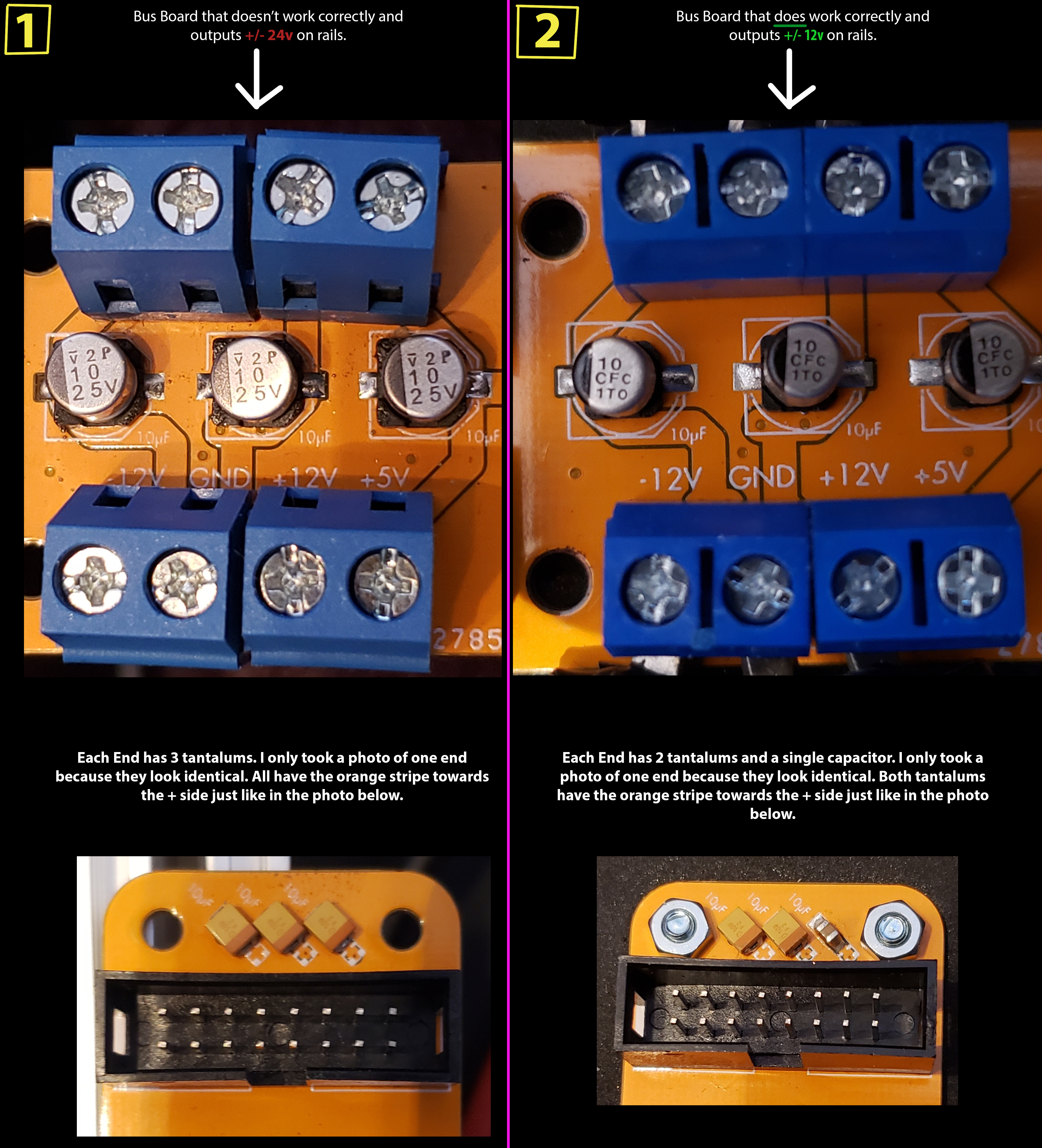
Yep…it was the bus board. I don’t have a clue why it is not working correctly. There’s only 9 capacitors on it aside from the 3 resistors that adjust LED brightness and all of them are put in exactly the same way as the bus board that is getting +/- 12v on the rails. The ONLY difference is that when Christian sent me the first bus board he included the 6 tantalum capacitors (3 on each end of the bus board) and when he sent me the 2nd one he had already populated the bus board with the capacitors. He didn’t use all 6 tantalums. He used 2 on each end and then had one a regular (non-tantalum) SMD capacitor on the 3rd slot on each end. Don’t know how else it could double the power output unless it’s this regular capacitor on each end of the bus board?
I’m afraid I still believe ±24 V to ground is an impossibility. If -12 V were connected to ground you could read +24 V and if +12 V were connected to ground you could read -24 V, but not both. None of this makes any sense to me as described. No, it can’t be the capacitors.
Thanks to all for taking a look at this. I don’t understand it either. I put a comparison image together here. I skipped taking photos of the resistors since they only are for the LEDs. So here are all of the connections between the two bus boards. Does anyone see anything here that would account for the +/- 24V vs +/-12v on one to another?
EDIT: I measured them exactly the same and it still came out +/-12v vs +/-24v
PS: @fredrik Thanks for the suggestion. I will figure out a way to cover the meanwells. I have some thin zip foam I could place just on the top of each? Or do these need to be able to vent and should I use something to allow for airflow?
How and where are you measuring the rails? If you put the black multimeter lead on the second screw from left in your picture (the one that’s marked GND) and probe with the red lead on, in order, the first, third and fourth screw on the terminal, what values do you get there? (make sure your multimeter is set to V DC).
I will figure out a way to cover the meanwells.
Having some airflow is a good thing, and the perforated cover isn’t a problem – it’s the bare L and N screw connectors that are dangerous. Even if you fill the case with modules, a loose screw or cable can cause all sorts of issues, ranging from shorting out the mains to injuring the person using it.
I had the black probe on the GND screw terminal and then I measured the rails with the red probe on the headers themselves. The other bus board came back with +/-24v and I measured the same exact way. I don’t get it.
I get the same +/-12V values by measuring the screw terminals themselves as well. I’m not using 5v so obviously that is 0.