Hi…I recently purchased a controller at a discountwhich I was aware had a faulty channel fader. I brought it home and it looks like someone had tried to replace or “fix” the fader and ended up cracking the board. I’m wondering if this can be fixed? There were some eyelets soldered to the pins which, I assume, was an attempt to fix a connection issue as it appears that the connection pads have been mercilessly rendered from their home on the board. I’ve posted some pics.
I apologize if this is not the right place to post such a request.
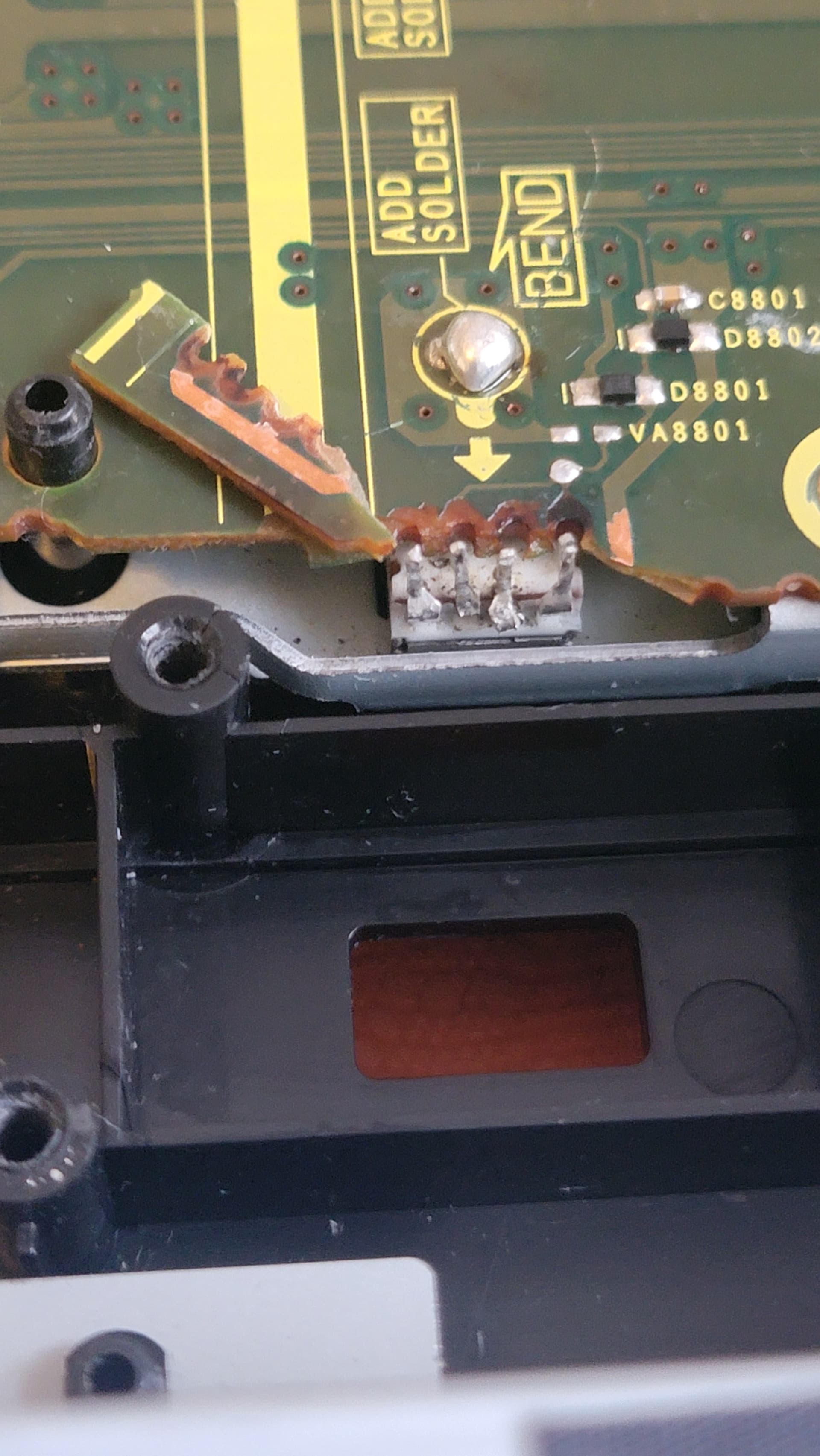
It should not be too complicated to add some patch wire to fix it, just examine closely the visible tracks on the PCB…
From the bottom pic, I think that the first and third pin (counting left to right) go to the exposed copper of the broken off large track on the right.
The second and fourth go to the round pad close to the pins.
Add a small blob of hot glue.
Is this fader on a mono channel ?
You should then look a bit closer on the tracks than what is visible in the pic.
But the principle is the same, follow the tracks to see where to solder the other end of the four wires…
when fixing my pcb “errors” I like to use enameled wire. for example those pins you could wrap the enameled wire around the pin, solder it, and then route the wire to where the next stop on the pcb would be. get some uv curable solder mask to paint on after you’ve fixed it and that will insulate it electrically. Also using extra flux helps immensely when doing any non thru hole repairs. it makes it so you can hold the thing your soldering in place with solder on the iron and the in solder flux can burn off and you still have a bunch of flux at the site your about to solder.