The first option should be “use a ±12 V power supply,” many of which are mentioned in this thread. Why isn’t that an option for you?
1 Like
I have a benchtop power supply, but it only has two terminals. Not sure if you’re referring to a benchtop supply, but I want this to work on it’s own. Are you talking about something else?
Look here:
2 Likes
Hi everybody!
I genuinely don’t understand why power supplies are so expensive. I am trying my luck with this very cheap solution:
A 120V to 5V adaptor https://www.cdiscount.com/bricolage/electricite/alimentation-12v-adaptateur-secteur-5-v-pour-dis/f-16614-auc0604923380043.html?idOffre=394870843
and a buck-boost converter from 5V to -12V and +12V https://www.amazon.fr/Sunnyflowk-Positive-Negative-Boost-Buck-Automated/dp/B0868FC992/ref=sr_1_1?__mk_fr_FR=ÅMÅŽÕÑ&dchild=1&keywords=5-30V+à+±+5V+%2F+6V+%2F+9V+%2F+10V+%2F+12V+%2F+15V+%2F+24V+Positif+Négatif&qid=1590054706&sr=8-1
Am I crazy? What could go wrong? Why is a microbus + 12VAC adaptater better?
The common design with AC wall wart + linear regulators gives you a smooth regulated low impedance supply for both +12V and −12V, with well defined characteristics for both voltages. They’re also easy to DIY from scratch, with widely available and inexpensive components, that are easy to understand and design for. So reasonably good, *and* DIY friendly.
Switched supplies (like the boost converter you link to) require more sophisticated circuitry, are harder to build on your own, and generate the different voltages by repeatedly charging and discharging inductors at high, hopefully inaudible frequencies. However, this overlaid high frequency may interfere with some circuits, which is why many avoid them, or add additional regulators after them. Also, the converter you link to use a single converter IC and some trickery to generate two voltages, which most likely gives worse regulation on one of them (the chip can only measure one of the output voltages, so if the load isn’t symmetrical (it never is in synth circuits) they’re likely to drift).
But TBH the only reason your solution is cheap is that you found an absurdly cheap 5 V adapter, and a no-name boost converter from a random chinese manufacturer, with no specifications and no schematics. A professional converter with the same specs would be more expensive (e.g. a similar MEANWELL DC/DC converter is maybe $25 but then you get an isolated supply with well-defined specs).
So your cheap solution may work, or it may be a horrible idea, the only way to know is to try it (and ideally look at the output under load with an oscilloscope). Most people are prepared to invest another 10 bucks or so on the most important component of their synthesizer, to know what they’re buying. And being able to build it yourself is a plus for many.
5 Likes
Hi Fredrik, thanks for the reply!
I am a newbie at electronics, I have just started with the simple VCO project. It is not working, but I don’t know if the problem comes from the module or the power supply (maybe both ^^).
Anyway, you are probably right, your remark about the single converter IC seams to make a lot of sense. I don’t see any variations with the oscilloscope (but, as you might have guessed, I use a crappy cheap oscilloscope ^^), but there is a small drift as you predicted.

I don’t know if this is actually the cause of my problem, but I think I will be more reasonnable and look for a proper power supply.
Cheers!
2 Likes
I don’t think the voltages you see there would prevent the VCO from doing at least something, so while a better supply is nice it won’t fix this on its own. Did you build stripboard version of the simple VCO? If so, checking the supply voltages on the 3340 and the CV voltages on the 100k resistors (not the 3340 pin) may provide more clues; see the drawing here:
(I’ve also marked some expected resistances there, but make sure to power off before measuring those.)
(and yeah, you can follow up in that thread or in one of the other simple VCO threads, since this is about power supplies).
4 Likes
A microbus board costs £12.00. The adapter costs under $15. Parts can be had for a few dollars more. Add it up, it’s maybe $40.
I fully understand $40 is a lot of money to some people, but compared to everything else in this hobby, it’s not. And given the importance of the power supply, it’s a bargain.
If you want to see expensive, look up what people are charging for assembled top end Eurorack power systems. Here for instance is a box with some rails and a power supply, for $700:
5 Likes
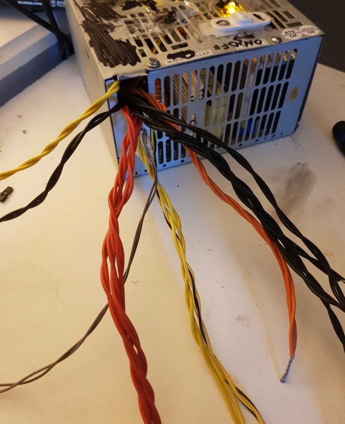
I actually use an old ATX power supply and that works well! I have +12V +5V for Arduino and stuff GND and -12V!
If you want to make it cut every connector put a switch or short the green wire with the ground (black wire) and you’re done!
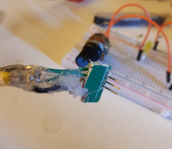
I connected +12V GND and -12V to male pins so I can use it on protoboard!
Also the wires are like that:
- yellow : +12V // red : +5V // orange: +3.3V // black: GND // blue: -12V // green: Power on to ground // purple: +5V standby // and the grey and the brown are not that useful
And you can make it cleaner than mine haha

1 Like
Another option is to use an adapter board, like
http://dangerousprototypes.com/docs/ATX_Brakout_Board_design_overview
or one of it’s many clones from aliexpress/ebay etc.
The issues with using switched mode supplies for analog circuits have been discussed elsewhere, so I’ll just mention that many PC supplies provide very little current on −12 V, so odds are you’ll run out of synth power long before you get anywhere even remotely close to 300 or 500 or however many watts that supply is rated for (just grabbed the spec for a random 700 W supply, and you can pull 300 mA of ±12 V from that, or ~7 W max from a 700 W supply. YMMV).
4 Likes
Ooh yeah I know that mine can deliver only 0.7 A but just for prototyping it’s fine I wouldn’t use that for a whole wall of modular haha. But yeah that’s the bad thing of it
3 Likes
Yes sure! But my first drive to do DIY is that it is cheaper than ready-made, so I am naturally aiming to the cheapest solution. As Fredrik pointed out, my solution was not really symmetrical, and a small voltage difference appeares when on load. Although it works so far, with just 1 simple VCO and 1 simple LPF, I will change to a AC wall wart + linear regulators solution to expand my setup with more peace of mind.
I have now found this kit for 10€ Velleman Kits K8042: SYMMETRIC 1A POWER SUPPLY – Velleman – Wholesaler and developer of electronics
Compared to the Microbus kit (£42.00), it lacks the +5V output and the bus board, but on the other hand it says it can handle up to 1A compared to 500mA for the microbus. I am giving it a go.
FC also has a lot more smoothing capacity (*) but otherwise that one looks like a straightforward LM317/LM337 config, with enough additional diodes and caps that it’s a robust implementation (a lot of people skimp on that). You need to do a bit of trimming (and those single-turn trimmers aren’t great) and look out for ripple/dropouts/brownouts, but otherwise it’s not an obviously bad choice.
(the other upside with FC is that it’s a field-tested design; some folks seriously underestimate the advantages you get as a newbie from using something that is Known To Work™  )
)
There’s no real difference in power rating, though; you need to add heatsinks long before you get even remotely close to 500 mA, and same heatsinks will give you roughly the same capacity with both supplies. Also make to make sure to isolate things well if you use the same heatsink on both regulators; their metal tabs are very different things, and connecting them isn’t a great idea.
*) iirc Kristian Blåsol has a video somewhere where he talks about the issues he ran into with only a single 470 uF per rail. May add it if I find it. Found it, see below.
3 Likes
Thanks again for all your good advice. Yes the price difference is small (although I have the full kit with 10€ instead of just the PCB for 12 GBP). I mainly ordered this one to save on shipping fees, as it was from the same French website where I order my electronic components (gotronic.fr)
Found Kristian’s Modular In A Week video that I mentioned:
")
(his fix there is classic MIOW style; I’d probably replace the ones on the PCB with something a bit beefier instead ![]() )
)
2 Likes
He came back to it later in the series to address the ripple. Basically adding a lot more capacitors, 4700s if I remember. He’s also got a very neat circuit board on his site (including the build files)
Neat power supply but I’ve stuck with the frequency central boards. Meh, six and half a dozen really (for non Scots that just means there is nothing to rate on which is better)
3 Likes
EDIT:
I deleted my stripboard layout because it was dangerous and doesn’t work as intended. Don’t bother with it. TL:DR I was dumb, the people below helped, please carry on.
Original post:
Hey all,
Coming back once again to hopefully have the stupidity schooled out of me:
I have a stripboard module that I just finished, but when plugging it into my power supply (I have an extra for the bench), my power supply starts acting as though there is a short circuit (i.e. the output voltage suddenly drops and the power regulators get smoking hot). I’m lucky this thing didn’t destroy my power supply - thankfully it works as usual when the module is unplugged, so It must definitely be the module.
Before powering on a new module, I always do the basic tests: use a multimeter to make sure +12v is not shorted to ground, make sure -12 v is not shorted to ground, and make sure + and - 12 v are not shorted to each other. Then out of paranoia, I plug the module into the power supply and repeat the exercise before powering up. This module passed, so I figured it would be OK.
Obviously I need to double check everything about the module - the layout I’m using, as well as the circuit board itself. But out of curiosity, do any of you know what kind of wiring error would cause these symptoms without creating a short circuit that my multimeter can detect? I’m hoping to narrow my search. I worked too long with too much coffee and too little food and now my brain doesn’t work.
Thanks for any insight everyone.
Cheers,
-Wes
EDIT: This is the stripboard layout, it is for a dual version of the expression pedal interface that Analog Output posted in another thread (the resistor values have been tweaked to suit needs/different pedal). I plan to share once it’s verified working and not exploding, but here it is for troubleshooting purposes. I recommend you don’t build it for now, unless you are smarter than me. I know the circuit works in theory because it was fine on the breadboard.
2 Likes
@analogoutput will be able to answer you better I do not know the diagram, but just a remark, 15 k for the led ? it seems huge to me, you did not reverse some resistance in your construction ?
1 Like
The TL072 rails are backwards, right? (unless you’re using red for −12 V in case your color coding is backwards, and your caps too  ).
).
EDIT: Also, a single 100k pullup for two separate jacks?
3 Likes
Since this has nothing to do with the power supply, I’ve replied in the expression pedal topic.
1 Like