thats cool , would have never guessed what that tool was for , can’t say I have ever seen one here in the states .
You mean other that an instrument of torture?
2 Likes
Hey! I have a 24V wall power supply power supply, can I buffer the half potential of the PSU to get a ground terminal? (In addition of a +12V and -12V in reference of the “virtual ground”)
Just like so:
In principle, yes, but that voltage divider is not every accurate. Here’s the schematic I use:

from: GitHub - TimMJN/Rail-Splitter: Buffered virtual ground circuit
The TLE2426 gives a more accurate virtual ground. You could always leave of the last BUF634 stage. In this configuration, it’s able to deliver 150 of 250 mA, depending on the BUF634 package you choose (with or without heatsink).
1 Like
Okay! Thank you a lot!
If I can get this component I’ll try it out it’s for a DIY spring reverb PSU
The rail splitter is $2-3/ea and the BUF634 buffer $15/ea in DIP, so perhaps not the most cost-effective way to build a weak power supply 
(ok, the BUF is cheaper in SOIC-8, but you can get a quality 2×12 V or 2×15 V transformer for about the same money as the silicon in this circuit. But for a self-contained unit, I’d also consider a DC/DC converter; may cost you a few $ more (but not a lot) but it’s a single module so trivial to integrate, and also handles other DC inputs (usually a 2:1 or 4:1 range), so depending on model you can power with e.g. a cheap 18 V laptop power brick or even USB…)
(but otoh, this also depends on why you need the virtual 0 V; if you’re just level shifting the internal signal levels, you may not even need an opamp…)
2 Likes
You are right, this is definitely not something you want to use as a main power supply!
I use it with my benchtop PSU to prototype modules, as it gives me current limiting. It’s cheaper than a second benchtop PSU for the bipolar supply.
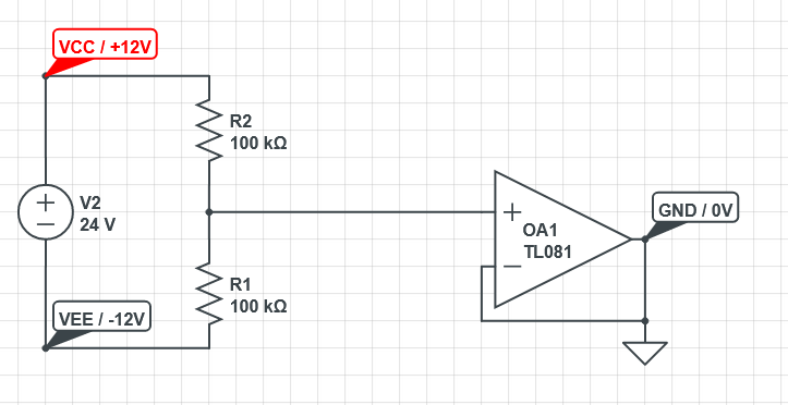
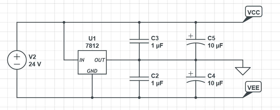
Well actually I made something even cheaper and functionnal! I was playing with the stuff I had laying arround and it seems like a 24V DC power supply with a LM7812 regulator does the job nicely for just a little board, it’s not really accurate but it doesn’t really matter I guess. I added some capacitors for filtering tho.
If it’s really bad then I’m gonna move on a better way to do it like you told me  thank you!
The 7812 cannot sink current, so that won’t work for the general case, unless you’ve invented a new topology. Schematics?
3 Likes

Yeah, post that to stackexchange and I suspect a ton of people will tell you it won’t work at all
Think about how the current flows through this circuit – there’s no route back to the 24 V supply via your virtual ground, since you cannot run current “backwards” through the 7812, so the only way for this to have a chance of working is if the load on the negative rail is guaranteed to always exceed the load on the positive rail with whatever current the 7812 needs to regulate (usually 5 mA), so that all current returns via the negative rail.
You’ll probably also get 24 V spikes on VCC when you turn this circuit on.
4 Likes
As Fredrik mentioned, the 78xx cannot sink current. This will only work as long as you draw current from the GND, not sink current towards it. I.e. it will work for a load between GND and VEE, but not for a load between VCC and GND. It will also work in the special case of I(VCC) = I(VEE). But then again, a voltage divider would also work in that case, and I wouldn’t cound on it.
1 Like
Hi,
I am exploring the world of diy gates, triggers, dividers mostly. I am a beginner so really first copying stripboard images then trying to understand it and add a little tests. But I have some tutorials in 5 volts. But currently, closer in +9v-GND, and then closer I have finished circuits with +12-GND but I would like to add the -12. Would I have to start the whole circuit or can I take some elements, pass them into an OP AMP and get the desired voltages?
Thanks in advance!
1 Like
An op amp cannot generate voltages outside its supply rails (most cannot even hit the supply rails).
There are ways to generate a negative supply rail from a positive supply, but they require non-trivial circuitry (and/or non-trivial PCB layouts).
I’d recommend getting a real supply, e.g. one of the frequency central ones. They’re cheap and easy to build and troubleshoot. See these threads for more pointers:
(might move this post to the latter in a bit)
3 Likes
And @TimMJN
Yeah that makes much sense now that you told me. Thank you for your explanations ![]() I think I’m stuck I wanted to make a spring reverb driver circuit but anyway it’s so so so noisy I can’t do anything with that
I think I’m stuck I wanted to make a spring reverb driver circuit but anyway it’s so so so noisy I can’t do anything with that
1 Like
are charge pumps really that “non-trivial”? it’s like an IC and two caps
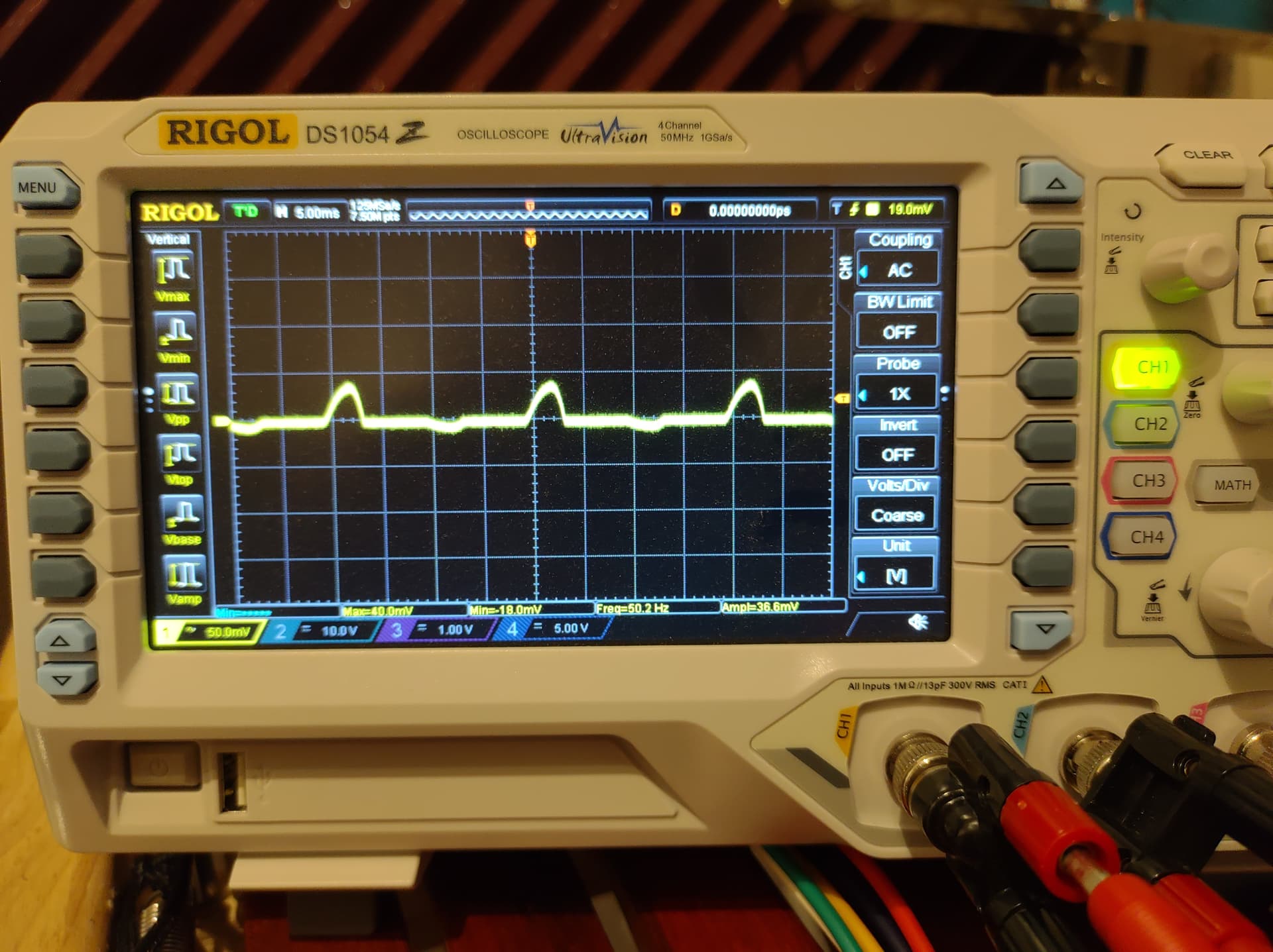
So last week I upgraded my case’s PSU, from 1x FC microbus and some passive bus boards to 3x FC routemaster. Much to my unpleasant surprise, I got presented a nice fat 50Hz hum after reassembling the whole thing. I noticed the hum emerged whenever I plugged two modules from different PSUs into eachother, so my immediate thought was: ground loops. I also unplugged each individual module to see whether one of them was giving problems, but no difference there.
Here’s a scope capture of a VCA with another (quiet) module plugged into it. The bumps are perfectly at 50 Hz.
Before I continue, here’s some info on my current set-up. I use a 230V/12V transformer with a single secondary winding, which is branched to 3 PSUs. See the pictures and makeshift schematic below.


Now, against better judgement, I had used 22 AWG wires to connect the PSUs to the transformer. This was my prime suspect. I unplugged the top two PSUs, and replaced the bottom PSU ground wire with 10 AWG (ain’t no kill like overkill). Unfortunately, the hum persisted.
I also plugged the supply rails into my scope. These are taken with only 1 PSU connected to the transformer, but that obviously still forms a ground loop between the synth and the scope.
+12V

-12V

Now, I understand why ground loops happen. What I don’t understand, is why they happen now, but not with the microbus. Granted, that was only 1 PSU, but I still connected it to external mixers etc without any problem or hum. Also, is this really a ground loop I’m looking at? Shouldn’t I see a perfect sine in that case? Is this just supply ripple? The routemaster is designed for a centre-tapped transformer, but the build guide also mentions using it with a single transformer.
Here’s the things I will try in the coming weeks:
- replace the transformer with a centre-tapped one
- replace all wiring with 15 AWG
- create more space between 12VAC and GND wires
If there are any more suggestions or ideas here, I’d love to hear them. Thanks!
4 Likes
Yeah - this stuff is a sub-branch of the darker arts, and I’m not all that well versed in it.
What do the rectified/filtered voltages look like on the input side of the regulators?
I’m not sure that phase matters, but it looks like you’ve got neutral (blue, right?) hooked up to pin 1, not live like in your schematic.
Good luck!
2 Likes
Thanks for your reply! I’m in the Netherlands, our mains plugs are non-polarised. So live and neutral are interchangeable. After the isolated transformer, it will indeed just be a phase shift. Cheers!
I have built mine with the center tapped transformers and not had a hum problem , hopefully that will help you too . not much technical to add and my situation is different as far as the mains 115 v and it is split , line - neutral - ground .
2 Likes