So last week I upgraded my case’s PSU, from 1x FC microbus and some passive bus boards to 3x FC routemaster. Much to my unpleasant surprise, I got presented a nice fat 50Hz hum after reassembling the whole thing. I noticed the hum emerged whenever I plugged two modules from different PSUs into eachother, so my immediate thought was: ground loops. I also unplugged each individual module to see whether one of them was giving problems, but no difference there.
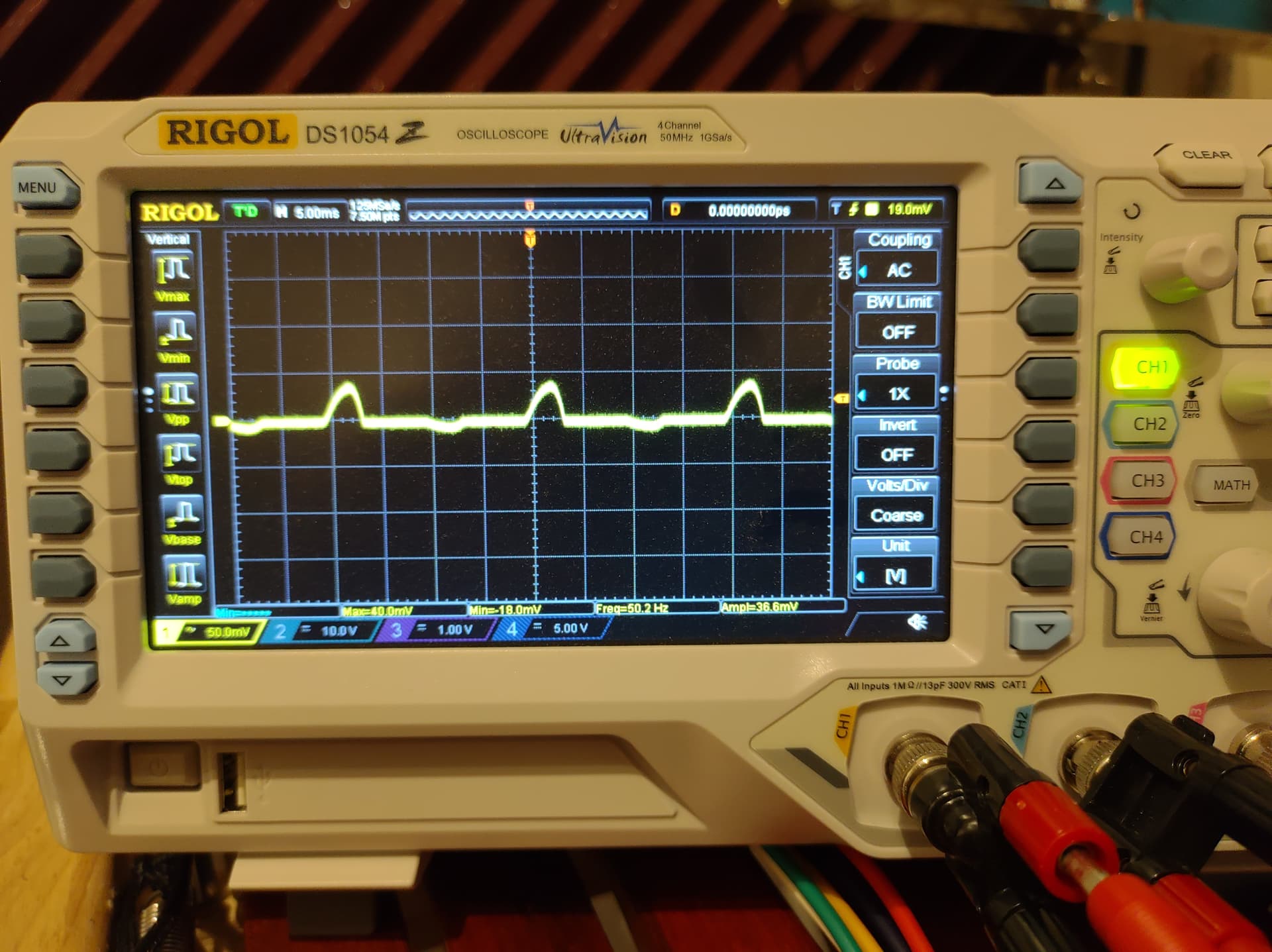
Here’s a scope capture of a VCA with another (quiet) module plugged into it. The bumps are perfectly at 50 Hz.
Before I continue, here’s some info on my current set-up. I use a 230V/12V transformer with a single secondary winding, which is branched to 3 PSUs. See the pictures and makeshift schematic below.


Now, against better judgement, I had used 22 AWG wires to connect the PSUs to the transformer. This was my prime suspect. I unplugged the top two PSUs, and replaced the bottom PSU ground wire with 10 AWG (ain’t no kill like overkill). Unfortunately, the hum persisted.
I also plugged the supply rails into my scope. These are taken with only 1 PSU connected to the transformer, but that obviously still forms a ground loop between the synth and the scope.
+12V

-12V

Now, I understand why ground loops happen. What I don’t understand, is why they happen now, but not with the microbus. Granted, that was only 1 PSU, but I still connected it to external mixers etc without any problem or hum. Also, is this really a ground loop I’m looking at? Shouldn’t I see a perfect sine in that case? Is this just supply ripple? The routemaster is designed for a centre-tapped transformer, but the build guide also mentions using it with a single transformer.
Here’s the things I will try in the coming weeks:
- replace the transformer with a centre-tapped one
- replace all wiring with 15 AWG
- create more space between 12VAC and GND wires
If there are any more suggestions or ideas here, I’d love to hear them. Thanks!