Sam (@lookmumnocomputer ) Requested all of these Diagrams… I happen to have what I believe is most of Caspers old site. at least the good bits.
Speak and Spell Circuit Bending Diagrams:

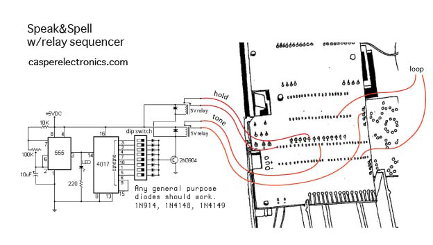
Hold Instructions:
The “HOLD” feature in the schematic above takes some fine tuning to get right. There are parallel resistors and buffer resistors, a pot and a switch. The values of the potentiometer and resistors for this feature are meant for reference only. I’ve found that they often need to be tweaked from model to model. If you are new to bending, don’t bother with the adjustment and the trim resistors, just wire the switch to the two “hold” points on the main board. The same goes for the “LOOP” feature. The adjustment lets you fade between loop and glitch effects, but it takes some tweaking. It’s much easier to take out the pot and resistor and just wire in the switch.
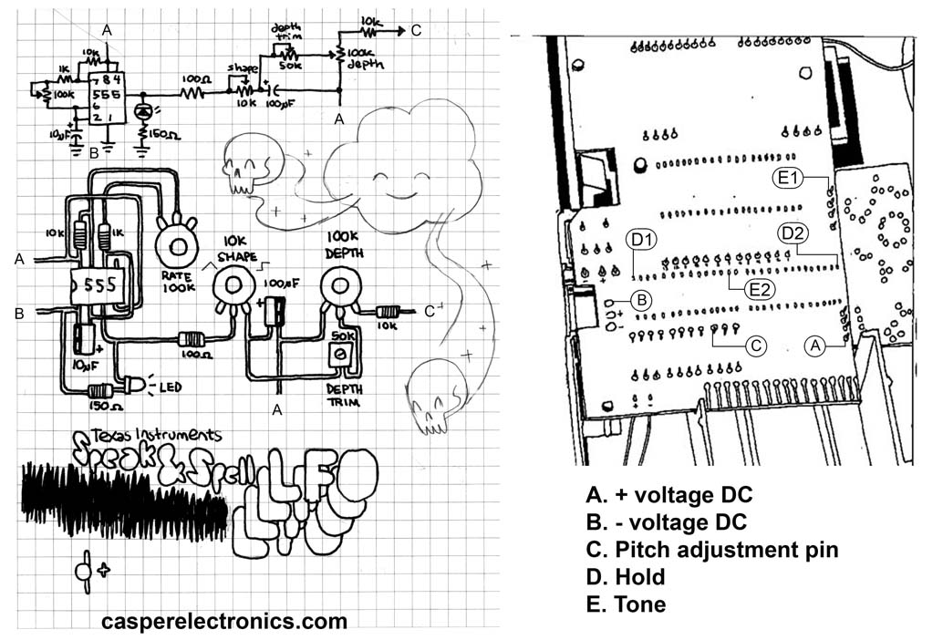
LFO Instructions (Boy I wish I read this 2 days ago when I had my Math open and it kept crashing)
The point labeled “C”. This is the pitch base point. COnnect this to the center leg of a 100k potentiometer.
Next connect the right leg of the pot to various points on the board.
You will eventually find a point on the board that makes the pitch higher when you turn the knob.
NEXT connect the left leg of the pot to various points on the board until you find a point that makes the pitch go down.
Now you will be able to make the pitch go up and down by turning the knob.

Pitch control is one of the most common and useful features that can be added to a majority of electronic, sound making device. It’s also one of the simplest to find. MOST simple audio circuits use a resistor mounted on the circuit board to determine the clock speed. Clock speed is the rate at which the circuit processes information. Basically the clock speed is the pitch.
Some circuits use other means of setting the pitch (clock speed) such as crystal or inductors. These are harder to modify. The following examples only apply to circuits which use a resistor to set pitch.
The first step in installing a pitch adjustment is to find the pitch resistor.
Below are a few rules and simple steps that will help you find the pitch resistor.
THESE ARE JUST GENERAL SUGGESTIONS. THERE ARE ALWAYS EXCEPTIONS AND ANOMALIES.
——————————————————————————-
LOOK AT THE BOARD:
The following technique most often works with very simple circuits like the example circuit to the right.
–Find the “BRAIN” of your circuit. This is usually a black blob. This blob is a cheap form of integrated circuit (or IC). These are also called “gum drop” ICs. An IC is a collection of microscopic electrical components working together to perform complex functions…like making sound. Some circuits use different styles of IC which look like flat black boxes with lots of metal legs. If this is the case, look for the box with the MOST legs. This will probably be the audio processing IC.
–Once you’ve found the brain, look for the resistor placed closest to the brain. 9 out of 10 times this will be your pitch resistor.
–Test your theory by touching the leads of the pitch resistor while the circuit is making sound. If you’re right, the pitch should jump up or down.
——————————————————————————-
LICK THE BOARD:
If you have a more complex circuit with lots of components you can try the “lick and poke” method.
–Lick the tip of your pointer finger.Turn on your circuit and activate a sound.
–While it is making sound, start touching the board with your pointer finger. Eventually you should hear a jump in the pitch when you touch a certain part of the board. Narrow down your search until you can identify a single point or two that effect the pitch. Maybe use your pinky instead.
——————————————————————————-
IDENTIFY THE PITCH BASE:
In most cases there is one lead coming off of the brain that is the pitch base point. By connecting this point to another point on the board (usually the positive or negative power supply) through a resistor you can set the pitch.
–Once you have found your pitch resistor you will need to determine which end of the resistor is connected to the pitch base and which is connected to the power supply.
You can usually do this by looking at the board to see if one of the leads goes to the power supply.
OR you can use a continuity tester to test both ends of the resistor to see if one is connected to the power supply. Or you can link your fingers and hold a metal pointer, like a jewelry screwdriver” and touch both leads of the resistor. Touching the end connected to the pitch base should result in a noticeable jump in pitch. Once you have found the pitch base, follow the diagram to the right labeled “voltage divider method”.
–It is less common, but sometimes the case that the circuit has two pitch base points. In this case both points will be sensitive and effect the pitch when touched. If that is the case, follow the diagram labeled “attenuator method”
——————————————————————————-
INSTALLING PEAK BUFFERS:
It is of utmost importance when installing a pitch adjustment that you install peak buffering trim pots or resistors. A buffer will limit how high and low the pitch can go.
I usually use potentiometers to find the correct buffering value, then replace the pots with resistors.
A buffer on the high end is most important. Turning the pitch too high for too long can burn out the circuit. Sometimes turning the pitch too high for just a second will fry it. In some cases no buffer is needed at all, but this is very uncommon.
——————————————————————————-
NON RESISTOR BASED PITCH ADJUSTMENT:
Some circuits don’t use a resistor to set the pitch. in these cases they often use a crystal which has a set (non adjustable) frequency. You can replace this crystal with a variable high frequency oscillator circuit.


Blank for drawing your own diagram.

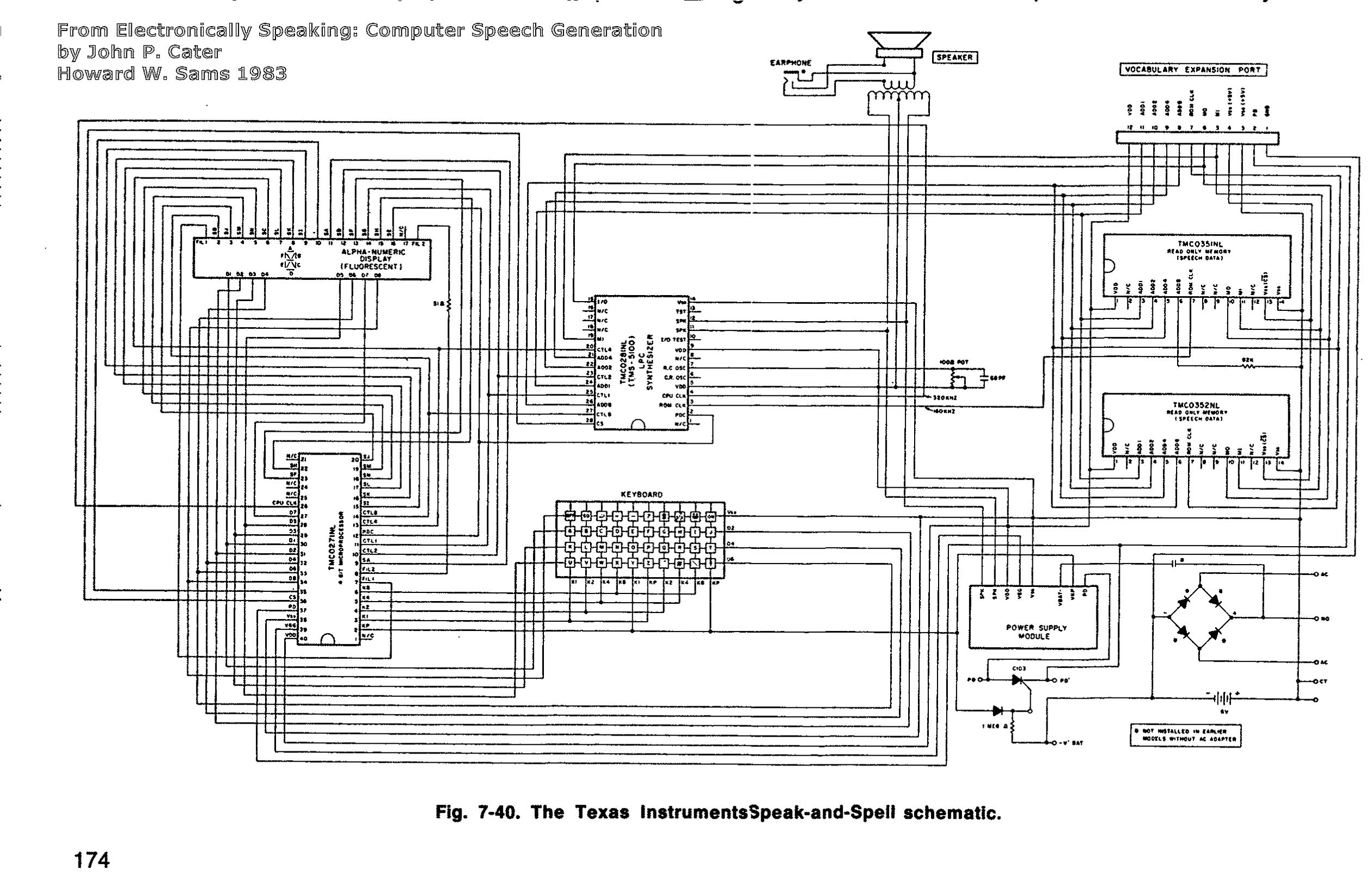
TI Schematic & Pinout
Bend Finder
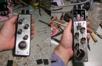
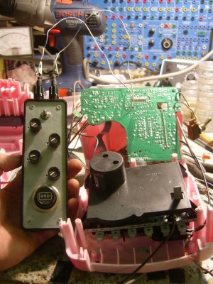
This is a simple but very useful little device.
It’s cheap and easy to build and can save you hours of time and frustration in the long run.
The Bend Finder has two main uses:
1- A safety buffer when poking around looking for bends.
2- Helps find correct potentiometer ratings for adjustable bends.
Just to clarify
I’ve gotten lots of emails asking about the BIG knob with the numbers on it. This is just a fancy potentiometer. It’s rated at 1000 ohms. The number read out tells you the exact resistance of the pot. I got it off an old, thrown out piece of test equipment. They cost $50+ new and I would not recommend buying one for this application. It’s very nice to have and it looks damn good, but definitely not necessary.

The bane of all benders is the burnt circuit. You spend hours finding those “choice” bends and just before wrapping it up you decide to try one more connection…And that’s when it happens. The circuit fries. A feeling of defeat grips your soul, your only release a single burning tear.
Using this little gadget can help you avoid these sad moments. Setting just a few ohms of resistance between your two test probes can greatly minimize the risk of permanent burn out.
It’s main use is to help find the best potentiometer value for bends that can be adjusted with pots. It can also be used as a simple, patchable switch.
-Solder two wires to two different points on a circuit board that you know create an interesting bend when connected.
-Connect those wires to the binding posts on the Bend Finder. Make sure the switch on the BF is in the OFF position.
-Turn all the pots all the way UP. Flip the BF switch to the ON position.
-Slowly turn the pots down one at a time starting with the highest value until you find the pot value that works best for that bend.
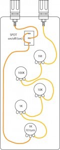
Basically it’s just 5 potentiometers in a box, wired in series with a switch.
I used two banana jack binding posts as connection terminals.
This is a common tool in most electronics shops. This model has just been tweeked a bit for use in a circuit bending shop.
Hopefully this helps some of you out 
")
