Haven’t examined the stripboard but a few comments on the circuit:
The 1M input resistor is unusual. 100k is more common and in principle gives a lower noise floor. NBD though.
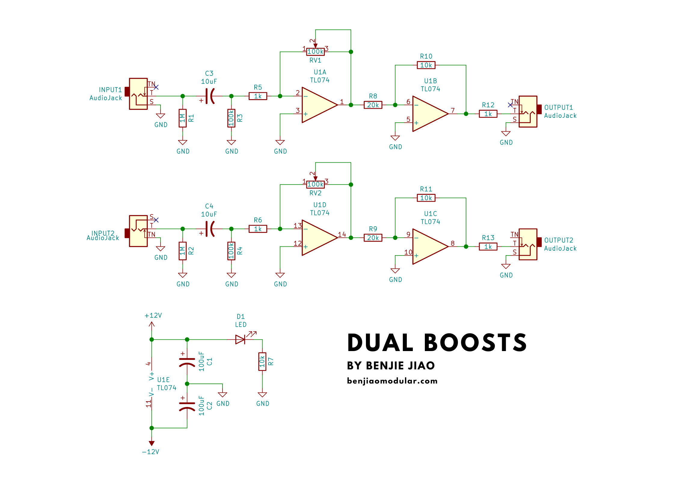
There is a stage with gain up to 100x followed by a stage with gain 0.5. That limits the output to 10 Vpp, I guess that’s the intent, but if you’re not plugging it into something downstream that can’t take more than ±5 V and has no protection (which would be a poorly designed circuit), you might not need that limit, in which case you could make R8/R9 10k and avoid the cut after the boost.
I don’t get the point of having an LED that indicates nothing but that there’s some voltage on the +12 V rail. Yeah, I know, my synth is turned on!
Good practice would be to add 100 nF bypass capacitors from each power pin of the TL074 to ground, ideally as close as possible to those pins. The 100 µF caps are 10x larger than what I usually use, but again NBD (if your power supply can handle it).
Added: I’ve looked at the stripboard just enough to notice C3 and C4 appear to be ceramic. Good luck finding 10 µF ceramics. Or are they tantalum? Whether tantalum or aluminum electrolytic, polarity matters and should be indicated on the layout, and you might need more space than what you’ve shown.
Also, in DIYLC you can decrease the opacity of the TL074 to show the stripboard cuts you presumably have underneath it.
Yep been pondering that! Will swap for 10k’s I think.
Yep. Gonna get rid of that!
I’ve got a big pile of these 106 capaciters. I won’t need to worry about polarity with those, will I? They’re just filtering, aren’t they?
I was hoping to use this with mostly guitars and occasionally drum machines and external synths. Is there a compromise for the value I should choose or should I stick to guitar level? Perhaps I’ll go with one 1M and one 100k for different inputs…?
I’ll make the tweaks with holes, values and wires this evening and post an updated schematic in an hour or two.
Thanks so much chaps. You’ve given my confidence a real boost!
The 1M input impedance is already a compromise for an electric guitar, as you would typically need multiples of that to match the impedance of a pickup. However, that 1M assumes that you will be plugging a guitar directly. If the guitar is preceded by a guitar pedal, it should not matter, as the output impedance of pedals is typically lower than that. Note also, that a grossly mismatched impedance might or might not be a bad thing. For instance, the Dallas Rangemaster treble booster had a rather low impedance input, which resulted in a mismatch that altered the tone of the guitar pickups resulting in that signature tone in its boosting of tube amplifiers…
Right, I was thinking about inputs for synth signals. For instruments 1M is indeed usual.
Didn’t know small 10 µF ceramics were readily available! I don’t know how suitable they are for audio signals (there are lots of considerations most of which I know little about) but probably OK. And unpolarized so not a problem.
Ok, wonderful. Will use those for audio in. (I have done on other modules previously and sounds good!)
Just thinking about the caps on the power supply line again…Would you recommend smaller 10uf electrolytics for that? That would reduce the power drawn by the module, right?
Hmmm! This is confusing me a bit! Would this sort of layout be a sensible way of attaching the caps close to the power lines of the Op Amp? The ground connections here hurt my head a bit! (Also using 10uf caps instead of 100uf?)
Measure the length and width of one of the 1/4w resistors that you have, then right click on a resistor in the layout and enter those values in the respective fields. This means that you’ll have to do it in each resistor, which is not efficient… I just did it once, and put a bunch of components in the right dimensions on a blank template. I use this template as the starting point, copying pasting from there instead of using the menus for such components.
Ok, first soldering attempt didn’t function. Just heard a little hiss when plugging it in! I decided I want to make it narrower and longer to fit nicely on the back of his Benjiao’s faceplate anyway. Back to DIYLC for a bit I guess!
Ok! Did a quick resolder and everything works brilliantly! Getting signals up to Eurorack level without distortion with just a little bit of amplification. Nice fat distortion if pushed.


