Arduino CV to midi CC

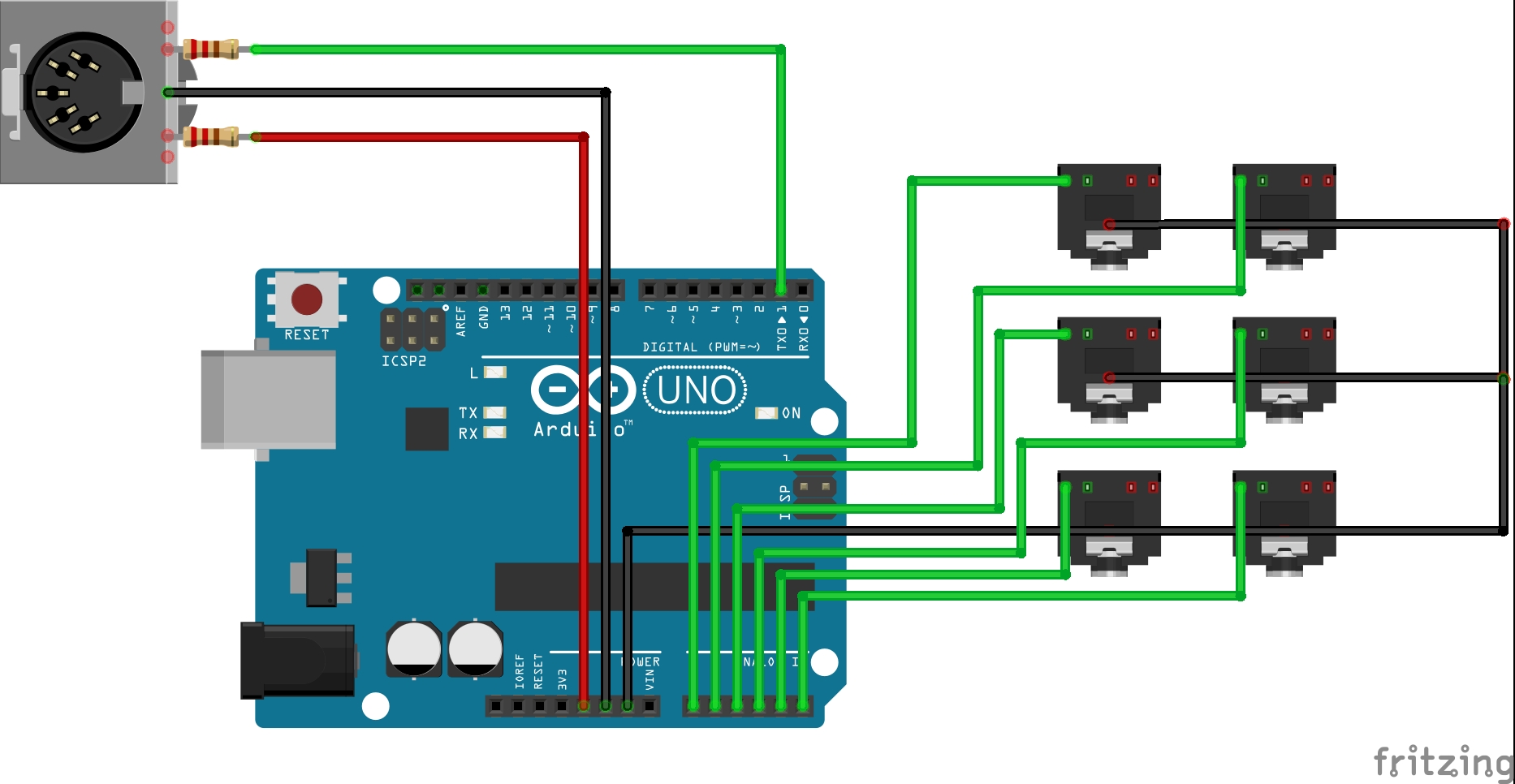
Hi all. I found this interesting code for the arduino. Which sends your 0-5v CV into a midi cc. So you can use it in ableton… Or whatever you want!

To give credit: https://forum.aemodular.com/thread/141/simple-cv-midi-converter-arduino

  //  Set MIDI baud rate:
  Serial.begin(31250);
  // not sure if I need this:
  pinMode(A0, INPUT_PULLUP);
  pinMode(A1, INPUT_PULLUP);
  pinMode(A2, INPUT_PULLUP);
  pinMode(A3, INPUT_PULLUP);
  pinMode(A4, INPUT_PULLUP);
  pinMode(A5, INPUT_PULLUP);
}
const int cvInputs = 6; // how many analog inputs are used
int cvLevels[cvInputs] = {0, 0, 0, 0, 0, 0};
int analogInputs[cvInputs] = {A0, A1, A2, A3, A4, A5}; // analog inputs
int midiChannel = 0; // MIDI channels 0-15 are 1-16
int midiCCnumbers[cvInputs] = {10, 11, 12, 13, 14, 15}; // define CC# for each CV input
int midiCCvalues[cvInputs] = {0, 0, 0, 0, 0, 0};
void loop() {
  for (int i = 0; i < cvInputs; i++)
  {
    cvLevels[i] = floor(analogRead(analogInputs[i])/8); // convert 10 bit analog input to 7 bit MIDI range
    // if cv has changed, update cv input value and send new midi cc value
    if (cvLevels[i] != midiCCvalues[i])
    {
      midiCCvalues[i] = cvLevels[i];
      sendCC(midiChannel, midiCCnumbers[i], midiCCvalues[i]);
      delay(50); // need to experiment with this delay some more, 50 is probably too long
    }   
   } 
}
void sendCC(uint8_t channel, uint8_t control, uint8_t value) {
  Serial.write(0xB0 | (channel & 0xf));
  Serial.write(control & 0x7f);
  Serial.write(value & 0x7f);
} 

I changed the code for the nano to this:

void setup() {
  //  Set MIDI baud rate:
  Serial.begin(31250);
  // not sure if I need this:
  pinMode(A0, INPUT_PULLUP);
  pinMode(A1, INPUT_PULLUP);
  pinMode(A2, INPUT_PULLUP);
  pinMode(A3, INPUT_PULLUP);
  pinMode(A4, INPUT_PULLUP);
  pinMode(A5, INPUT_PULLUP);
  pinMode(A6, INPUT_PULLUP);
  pinMode(A7, INPUT_PULLUP);
}
const int cvInputs = 8; // how many analog inputs are used
int cvLevels[cvInputs] = {0, 0, 0, 0, 0, 0, 0, 0};
int analogInputs[cvInputs] = {A0, A1, A2, A3, A4, A5, A6, A7}; // analog inputs
int midiChannel = 0; // MIDI channels 0-15 are 1-16
int midiCCnumbers[cvInputs] = {10, 11, 12, 13, 14, 15, 16, 17}; // define CC# for each CV input
int midiCCvalues[cvInputs] = {0, 0, 0, 0, 0, 0, 0, 0};
void loop() {
  for (int i = 0; i < cvInputs; i++)
  {
    cvLevels[i] = floor(analogRead(analogInputs[i])/8); // convert 10 bit analog input to 7 bit MIDI range
    // if cv has changed, update cv input value and send new midi cc value
    if (cvLevels[i] != midiCCvalues[i])
    {
      midiCCvalues[i] = cvLevels[i];
      sendCC(midiChannel, midiCCnumbers[i], midiCCvalues[i]);
      delay(50); // need to experiment with this delay some more, 50 is probably too long
    }   
   } 
}
void sendCC(uint8_t channel, uint8_t control, uint8_t value) {
  Serial.write(0xB0 | (channel & 0xf));
  Serial.write(control & 0x7f);
  Serial.write(value & 0x7f);
}

So why will this only work with the uno. I have almost no experience with coding or arduino’s…

1 Like

Tip: to avoid discourse messing up the indentation, use ``` (three backticks) before and after code segments, not > (that’s for block quotes)

This gives you:

void sendCC(uint8_t channel, uint8_t control, uint8_t value) {
  Serial.write(0xB0 | (channel & 0xf));
  Serial.write(control & 0x7f);
  Serial.write(value & 0x7f);
}

instead of

void sendCC(uint8_t channel, uint8_t control, uint8_t value) {
Serial.write(0xB0 | (channel & 0xf));
Serial.write(control & 0x7f);
Serial.write(value & 0x7f);
}

3 Likes

Not sure you need the internal pullup, or in fact if it even works on the analog lines.

Does it compile?

What are you using to see he output? just the serial monitor?

2 Likes

Seems they’re there and they do work, but you probably shouldn’t use them if the point is to read analog values:

The analog pins also have pull-up resistors, which work identically to pull-up resistors on the digital pins. […] Be aware however that turning on a pull-up will affect the values reported by analogRead().

https://www.arduino.cc/en/Tutorial/AnalogInputPins

3 Likes

I tested it with the uno and it seemed to work fine.
It also compiles and uploads fine.

I just directly tested it in ableton to see if I got a midi signal.

Try using Hairless Midi to see what is being received.

Also your UNO may have an FTDI serial port and the Nano a CH340 which may not be fully supported .

1 Like

Thanks. Will try it.

I did measure the tx1 output on the nano and it gave a constant 5 volts (or 4.7… but it’s the same as my 5 volt output)… No idea if this means anything. But thought I would throw it out here. It changes 0.1 volts when changing the input voltage on the analog input. Again. No idea if it means anything.

Will also delete the pullups on the analog inputs.

I’ll update if I have some new info.

Nanos can drive classic MIDI (DIN 5/180 connectors) just fine, assuming you wire them up correctly (TX via 220 ohm to one MIDI pin, 5 V via 220 ohm resistor to the other). MIDI over USB is trickier, since different Arduinos (and clones) use different ways to talk USB.

2 Likes

mmm… In my setup I’ve got a 2.2k from the tx1 to the midi din and 2.2k from the 5v to the midi din… Should I change it?

Midi over usb didn’t quite work. Seems like my arduinos weren’t capable…

2.2k is 10× too high, but spec does have 220 ohm on both lines:

Not sure if my builds have that :slight_smile: but probably a good idea to do what they say if you’re going to plug this into expensive gear.

1 Like

Mmm… Maybe I misread the values. I’m assuming expensive equipment has protection. So worse case it’s replacing an optocoupler?

Behringer often don’t. Mackie never has. Moog are a law unto themselves. My advice is to always assume the worst, test it first, then buffer or attenuate it anyway. I never got a sense of job well done from damaging other kit. Play nice

3 Likes

The 2k2 resistors’ value are higher therefore the current will be lower. So this will not damage anything. But the current through the opto coupler is 1/10 of what it is meant to be, which may have an effect on the voltage level of the data received.

3 Likes

Ahh had not relaised you were doing direct MIDI.

I just use USBserial, no library. Which as I say used Hairless. I did not try it on a nano but on a can’t think why a basic USB serial would be any different.

Rob

1 Like

Changed baud to 115200… Because got unexpected bytes… This seemed to be resolved by changing it.

Without pullups, I get randomn info from all analog inputs…

With pullups… I only get a signal from a jack socket I have plugged in. But it’s constant jitter and high values… Looking further! Feels like there’s an easy solution.

I think you need to separate two problems:

  1. check if the analog readings are what you expect them to be: disable midi and just print out the values via serial print. With this you can make sure if you need the pullups etc. I don’t think you need them, but maybe you can show your schematic?
  2. check the midi connection: just send known midi commands to you computer and check if they arrive not involving any analog readings, just some static stuff like this
sendCC(10, 10, 50);
2 Likes

I remember when I was doing my Midi controller I initially got random crap on the analog lines. In my case it was due to the +V analog supply line being too high, it needed to be the same as the internal operating voltage of the duino.

I think there are 3.3v or something versions of some arduinos, so 5V CV would be too high.

Rob

2 Likes

Ok. A lot to check out… In the mean time my very simple setup:

(didn’t find mono jacks in fritzing… But you get the idea.)

1 Like

What’s showing unexpected bytes? the baud rate was correct.

I would do what Sebastian says and ditch the midi and use the Arduino Serial monitor to see what’s coming in.

2 Likes

Yup! Thank you… Just checked analog readings… That’s where the problem is. Getting weird analog readings. (plugging in from the lfo and envelope from my ms20…)

I put in my trusty keystep to provide voltage, and this gave me accurate readings. My ms20 did not… I’m going to read the voltage once I can get to my multimeter.

So if I plug in from the pitch from my keystep I can reliably control it.

Edit: nvm… Made a mistake… Woops

Edit: edit: Ok… So I read the data from and it just gets an lfo in… it goes high and low and high and low… Constantly… doesn’t matter what voltage I put in.

Edit:edit:edit: This is the code I’m using to test analog input A3.

int analogPin = A3; 
                    
int val = 0;  
void setup() {
  Serial.begin(9600);           //  setup serial
}

void loop() {
  val = analogRead(analogPin);  // read the input pin
  Serial.println(val);          // debug value
  delay(100);
  }

When I unplug, it gives out randomn values

Editx5: Oh my god! I forgot to ground everything… Have everything hooked up, but forgot the final wire… Oh my… Oh freaking my… I always check… Apparently this was too simple…

3 Likes