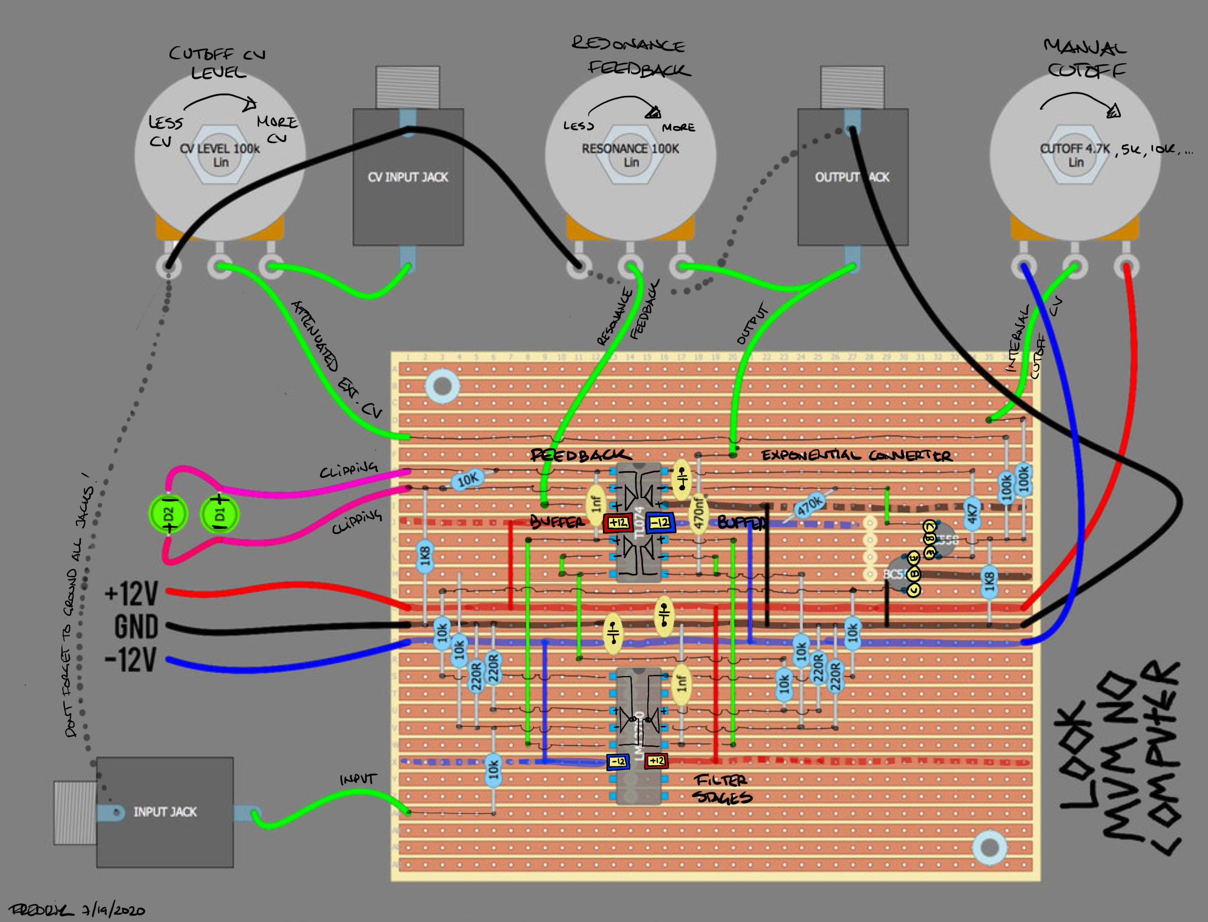
I did some scribbles on top of the LMNC low pass stripboard layout, showing what’s inside the chips, where the power rails are, what voltages to expect on the supply pins, etc. Posting it as new topic to make it easier to link to it
If you want add another INPUT : add another Jack and10K resistor to pin 4 of LM13700
If you want to add Levels to the Input, copy the CV Level 100K potentiometer idea (Attenuator)
There is no connection to GND at the Input Jack, maybe add it who have no misunderstanding ?
With those scribbles it starts to look like an oddly drawn schematic. Which is a good thing since it makes it easier to understand the circuit if you are not familiar with the schematic.