I need to build a little op-amp circuit on a single rail +5V
It needs to have variable gain.
I can’t find an example on internet that actually works. Very confused,.
I need to build a little op-amp circuit on a single rail +5V
It needs to have variable gain.
I can’t find an example on internet that actually works. Very confused,.
I could show you a circuit for that! It’s pretty easy to build and understand, why do you need it? 
Sorry to hijack but I’m also looking for a simple op amp circuit and getting confused. Either 5V or +/-12V is fine. I’m looking to boost the signal from a signal generator thats a couple of hundred mV up to a volt to something suitable for synth so maybe gain of 5.
Yeah, that’s a bit puzzling because the only thing you have to do is to replace the feedback resistor with a potentiometer.
(…but are you sure the problem is the gain and not that you get too close to the rails on the way in or out? What opamp are you using?)
The supply voltage that you put on the opamp just set the “limit” of your opamp. You won’t be able to output more or less voltage than the supply voltage
My supply voltage is +/-12V.
Basically I want to build the image here but I don’t know if there’s any ‘real world’ gotchas because I haven’t used an op amp before.
This is an inverting gain setup, you need to “re-invert” the output signal to get the perfect image of the input gained signal
Thank you, that’s cool I don’t think it matters but I have designs for non-inverting too 
I’ll give it a go
For a single supply and positive-only input use an LM358 (dual) or LM324 (quad) or similar op amp that is designed to operate down to 0 V on single supply. If your input is bipolar then you need to offset it.
For dual supply you can use TL07x.
I think I may have been over complicating things far too much.
The requirement is to set present levels on 3 audio sources so they match.
All devices in the circuit are powered from either 5V or 3.3V single rail.
I was using a TOL7x so as Rich points out not ideal.
All the examples I was following I think expected a bipolar signal. and biased the voltage.
Revised plan, make a simple micro mixer with a LM358 just as a buffer.
Thanks for all the input .
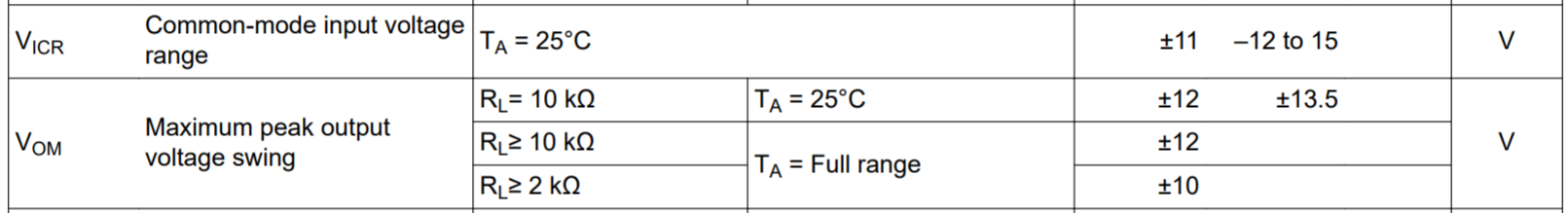
This bit from the datasheet explains why (the values are min and typical, for a ±15V supply):
Note that the valid input range starts at 3-4 V above the negative supply, so using a single 5 V supply doesn’t give you a lot of range…
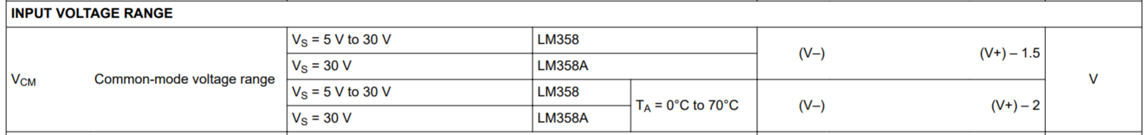
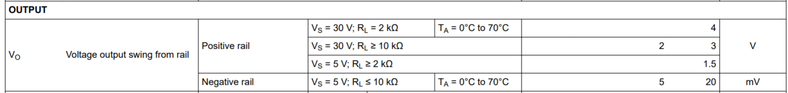
Same parameters for LM358 (here given for 5 V and 30 V supplies):
Note that the TL07x input range is relative to the negative rail, while the LM358 is relative to the positive rail. This reflects the design of the input stage; basically on which side of the input amplifier the bias current circuitry is (which needs a bit of voltage to work). True rail to rail opamps often have two separate input stages in parallel, to get full coverage.
Can I ask a favour??
I’d love to see a simple op amp inverting amplifier stage something like a TL072 on a breadboard or similar so I can compare with what I’ve been trying to do and trouble shoot. If anyone has a photo/ doesn’t mind taking one!
All I get out is 50Hz hum. I’m going to be away with work for a while but it’d be great to at least learn something before I go!
I find it really helpful to be able to compare schematics with physical builds
The schematic is really simple:
Connect the input to resistor R1 and the other end of R1 to pin 2. Connect the output to pin 1. Connect a resistor from pin 1 to pin 2. Connect pin 3 to ground, 4 to -12 V, 8 to +12 V.
That’s it for one stage but if the other op amp is unused it’s best practice to connect pin 6 to pin 7 and pin 5 to ground.
Gain is -R2/R1.
A photo isn’t any clearer than a schematic. If you’re having a problem, what would help is if you posted a photo, top and bottom, so someone can look for errors.
This is super helpful, thank you. as far as I can tell, I did what you described but I’m going to start fresh and look for any errors/ omissions. If it doesn’t work I’ll share some pics
I was connecting the negative side of the input to the inverting input of the op amp, rather than just straight to ground. I’m getting some amplification now Progress! Thanks again