Could you post some pictures of the front and back of your module?
What do you have hooked up to the different sockets of the module?
The Bounce Bounce module itself does not produce a sound. The Bounce Bounce merely provides a control voltage (CV) when being triggered by a low frequency oscillator, trigger sequencer, or anything else. That CV can then be used to, e.g., open a voltage controlled amplifier (VCA), so that the VCA passes along a sound that is plugged into it. The opening of the VCA can then somewhat resemble a bouncing ball sound.
Great, I will post photos when I’m back home, thanks for the reply!
When you say different sockets of the module, do these HAVE to have a CV input going into them and then the pot next to them is a depth of that signal control, or should I just be able to change the level of each control without needing an input for each socket?
No, not all sockets need an input. The Bounce has two output sockets. In order to trigger it, you can toggle the momentary switch for manual control, or have an input gate/trigger in the trigger socket to trigger it automatically.
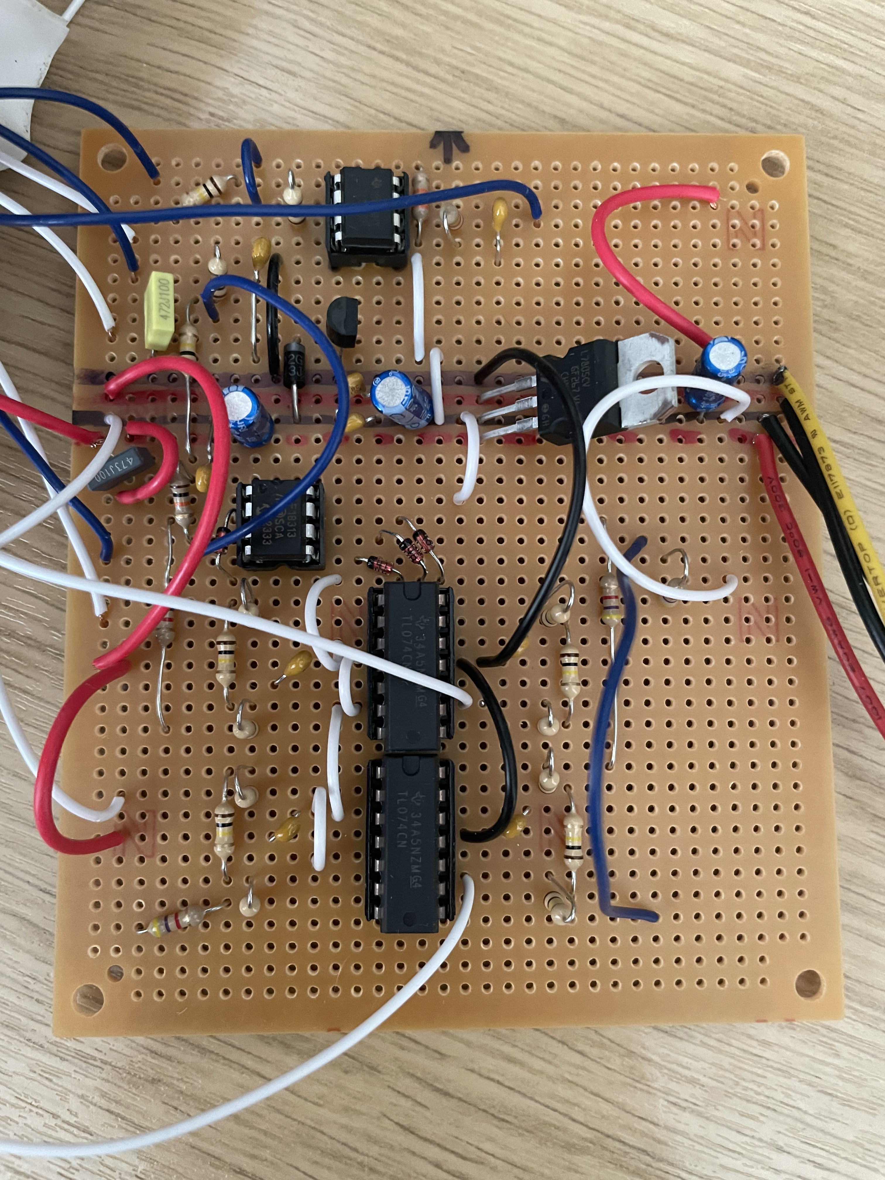
I should have pointed this out, these wires are for my power in, the red wire is +5v, bottom black wire is GND, top black wire is +12v and yellow is -12v.
I looked at the diagram after making the module and realised that the 7805 mosfet steps the +12 down to +5 anyway and so have run it without the +5 being wired into the module and it still isn’t working. I assume that I do not need an external +5v coming into the module and I can just use the + and - 12v?
Yes, 7805 is a 5 V voltage regulator (not a mosfet) and is intended to make the needed +5 V. It’s a little confusing in the layout diagram to have what look like PSU wires connecting to ground and +5 V, no such connection is needed (or desired, in fact).
Added: I guess those are meant to represent wires carrying +5 V off the board to the pots. I still think it’s confusing. I know I was confused.
I’m not sure if I understood your question correctly.
In the project, the 7805 (its a voltage regulator not a mosfet) provides the +5V needed for the circuit. It powers the Druid OneShot Chip. You don’t need a external +5V supply.
A question:
Did you purchase your chip (PIC) from this link?
The reason for the question is that I don’t see the “Druid ONE SHOT” label that usually comes stuck on the chip. Just as shown in the link’s image.
Did you check for shorts between +12v/-12v/GND/+5v with a multimeter? And did you check in all places that are connected to those, whether they have the correct voltage?
The TL074 on top: what is the second white wire on the left connected to? It seems to connect pin 6 with either pin 3 (GND) or pin 4 (+12V), neither seem right according to the schematic.
Ah, so the schematic for the stripboard version of the 1153 Bounce used by Projectionist1 seem to originate from this message from Dud.
@Dud Could you double check the left hand wires of the top TL074 in your build, being the black wires in your schematic? They do not seem to correspond with the original schematic of LMNC.
Yes, great thanks guys, that’s what I was thinking. I also did purchase the one shot from electric Druid directly, so shouldn’t have issues there, will triple check I placed it in the circuit the right way round but would have double checked this when making it the first time
Just an update on this, it works great now, getting all sorts of weird and wet sounds but applying the output to a filter cutoff.
HUGE thanks again @peternoya@analogoutput@SynthesiS@Dud


