but the original Matsumin diagram is for 9V and the other for 12V
1 Like
Yep, I overlooked that. But assuming that would be the same, I was wondering whether one can assume that a tube acts like a sort of voltage controlled current source and given a 200k resistor would result in higher voltage variation at its cathode than with a 100k resistor present. My knowledge of tubes is very limited.
Btw C2 is also smaller than in the Matsumin diagram, so that will also have an effect. Too bad that the falstad simulator doesn’t list tubes.
My knowledge of tubes is very limited too
Hi, I used a bc456b ( which is of the same family as the 457) and also added the caps as suggested by Jos and it really worked well. Right After plugging the module it sounded really mellow but after a few minutes, when the tube warmed up it really started to sing!
Did not add the feedback, will do this maybe later
1 Like
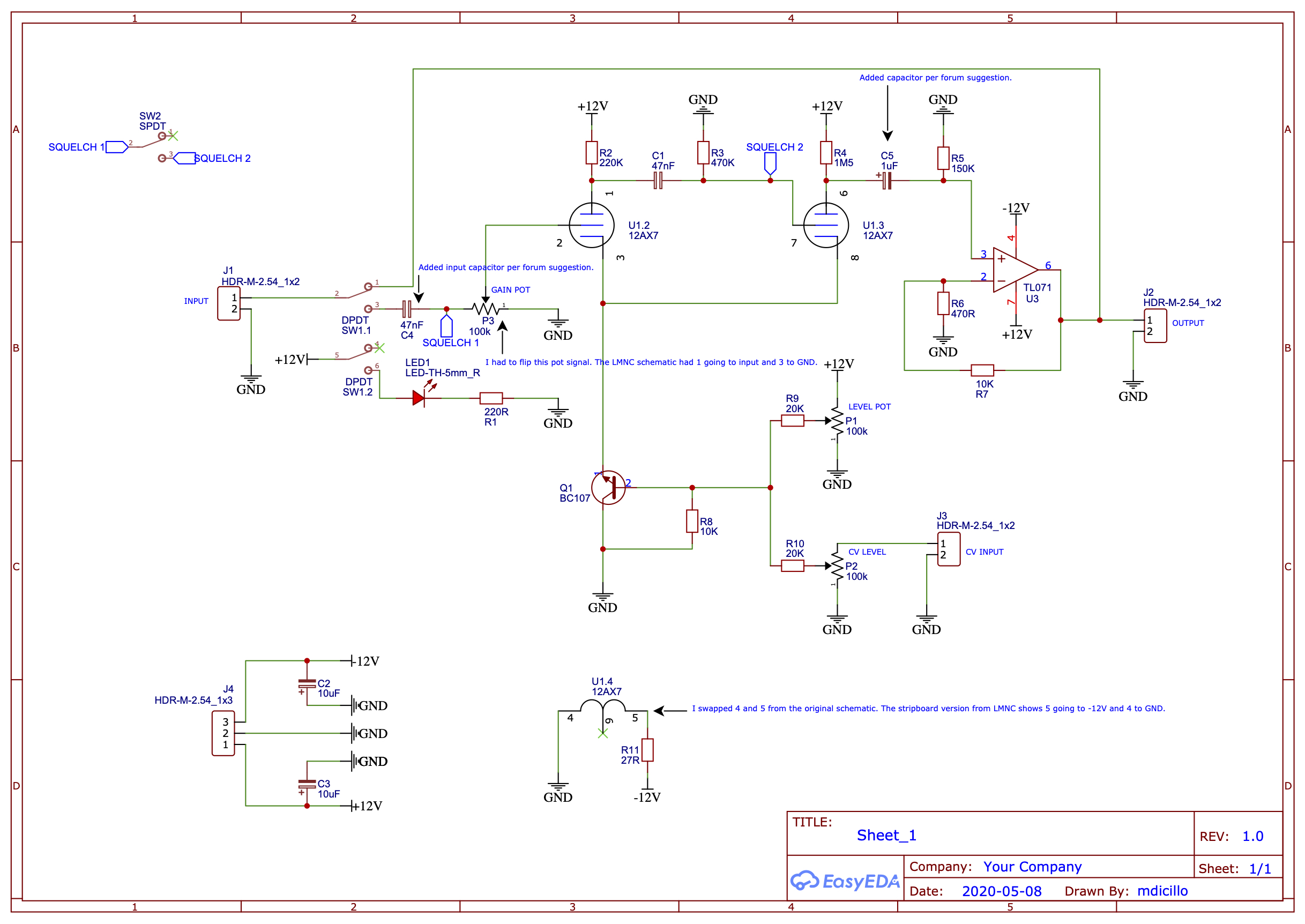
Hi all, I’ve tried building this from Sam’s schematic three times now without it ever working. I made changes that I noticed between the strip board and the schematic. Then I found this thread!
Can anyone take a look at this schematic I did and double-check it? I made the changes discussed above, (input cap, pin 6 to op amp cap) as well as fixing the discrepancies between the strip board and schematic.
Should this work now?
Thank you!
1 Like
Given that there are so many schematics knocking about that are untested or just drafts and that people and search engines do not read posts but do pick up all kinds of schematics, I think it would be wise to add some text in the schematic commenting on its status, like DRAFT or UNTESTED or TESTED or FINAL or something similar. I’ve posted this in other threads on this forum as well. I hope this will be picked up by everybody posting schematics or strip board layouts in the long run.
3 Likes
It is a schematic, so there is nothing wrong with the way you drew it, but given that it is customary to draw GND connections downwards you could make the schematic more easy on the eye if you draw the GND connections of R3 and R5 downwards by e.g. drawing the resistors “hanging” from the line connecting C1 to the tube (resp. the line between C5 and the opamp).
I may have asked this before, but given that Q1’s emitter and collector seem to be reversed, what is it supposed to do?
In my version of the circuit R5 is a potentiometer with the wiper connected to the + input of the opamp. This will allow you to control the signal volume at the output of the circuit.
2 Likes
Hi Jos, thank you for your reply! I’m only really familiar with the schematic through the LMNC site and I’m just trying to build what he’s done, but the schematic doesn’t seem to match the final product. I really should have redrawn the schematic in the proper format, but I was trying to keep it as similar to the one on the site so other people could follow along.
Since I’ve added the input capacitor and the capacitor after pin 6, as well as made other corrections between this schematic and the strip board version, does it seem like these are the solutions based on the conversations from this thread?
The bypass is not disconnecting the output of the op-amp. A double switch would do the trick. Apart from that I can only repeat what I said: the rest looks good to me apart from the missing output volume potentiometer and the reversed BC107 I do not understand the meaning of.
Ah, yes…I will add a double switch to the schematic. As for the volume pot, I may add that as well as an option. Personally, I use a mixer module, so I don’t have a need for a separate volume control on this one. But, it’s a good idea!
1 Like
Ok, I added a 4PDT switch to the schematic to handle the connection/disconnection of both the input and output, as well as the connection/disconnection of PIN 5 of the heating filament. Is that what you were referring to? I used a 4PDT because I’d rather do everything with one switch…that shouldn’t cause any issues?
I also added “DRAFT” to the schematic and fixed the ground symbols as you mentioned. Thanks for pointing that out!
I also added text for the optional potentiometer at R5.
How does she look now?

the reversed BC107 I do not understand the meaning of
From Sam’s schematics:

Reversed transistors tend to have a much lower gain (hFE) and iirc also lower Vce(sat), and I’m sure a bunch of other things also changes.
4 Likes
There will hardly be any current flowing from the tube’s cathode through the emitter I guess? Does it conduct at all in this setup?
1 Like
Yes it does work, in some “degraded” way.
See here :
https://learn.sparkfun.com/tutorials/transistors/operation-modes
and
Eric M.
2 Likes
please let me know if you find any decent 4PDT switches! ive been after some for ages. how I do it it put 2 DPDT switches next to each other. sometimes even gluing a bit of wood between the switch shafts so they become the same switch!
1 Like
also I remember going to one of your gigs! in like 2008 or something. I’m trying to remember where it was!
I was going to order these:
But, it looks like they’re out of stock right now. I’ve ordered a ton of switches and knobs from them and they’re always top quality.
I’m going to try these from Amazon (I think they’re the same, but more expensive!):
Either way, I have yet to try this updated schematic out, but as soon as I do, I’ll let everyone know! Maybe we can put a “CONFIRMED” stamp on that schematic finally!
3 Likes
I hope it goes well!
I’ll definitely be giving this a go once someone braver than I proves it works!
1 Like
So… after a very uneventful weekend I was bored enough to bite the bullet and have a go at making a strip-board layout of @casiokid’s as of yet untested schematic.
I’ve used two 2-pole switches for the bypass and turn off function as that’s what I’ve got ‘in stock’.
I’ve checked it through a few times for errors (differences between my layout and the schematic) and can’t find any(more). So I guess next up is turning on the soldering iron!

lotsa spaghetti
4 Likes
Nice job!!! I actually have the PCB for the “draft” schematic on order. It should arrive this week. I took a gamble and just ordered it thinking enough eyes have been on it that it should work, right? What could go wrong? LOL. Plus, with the prices of PCBs being so low, it’s more worth it for me than having to solder strip board. As soon as I build it, I’ll update this thread!
2 Likes