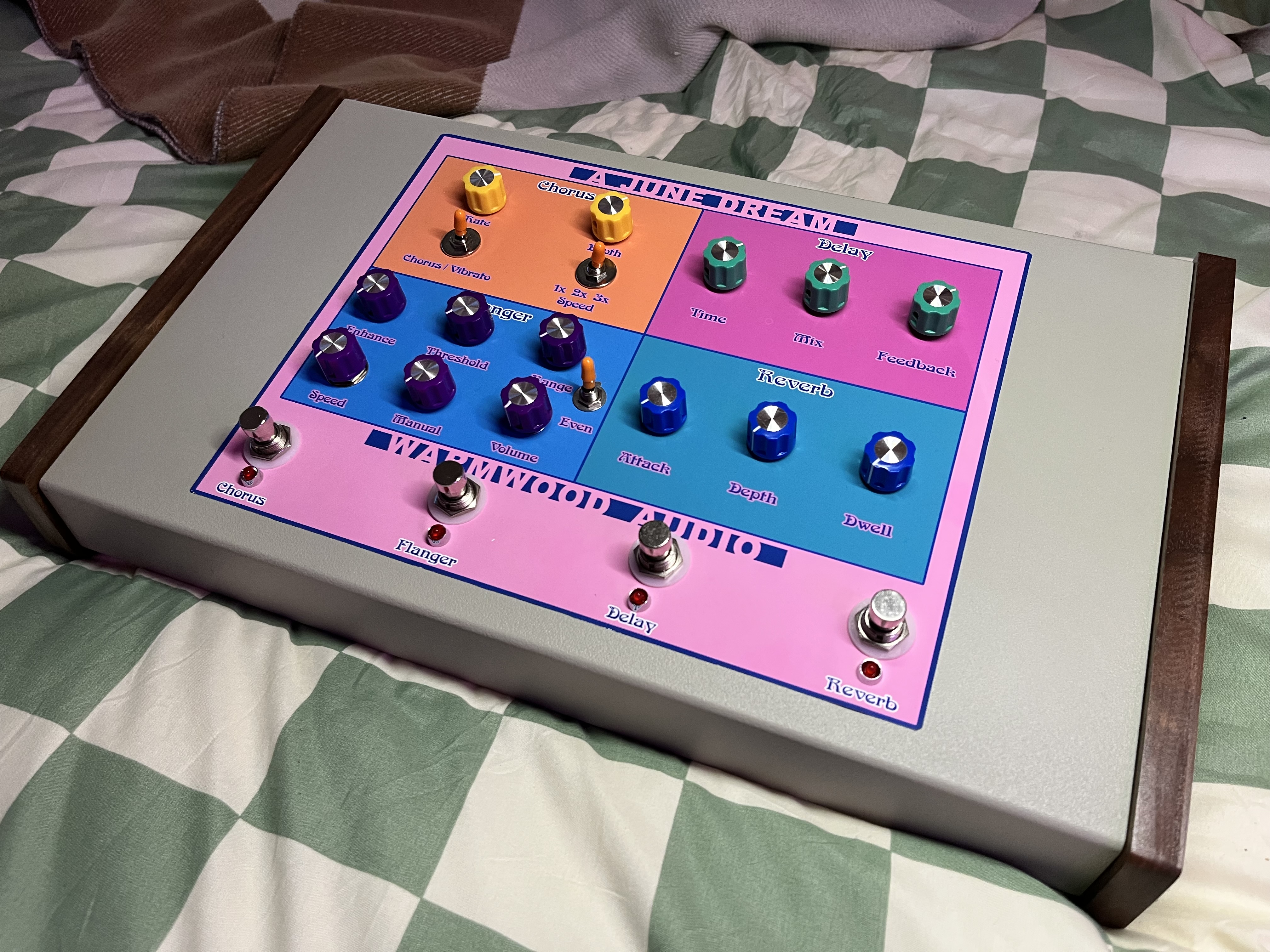
The chorus, flanger, and reverb all function wonderfully. I am having two very minor issues I am hoping someone could help me with. The delay’s 3mm LED is the only one that lights up, and incidentally, that board worked for a while as well but is now seemingly dead. While I was checking the other three effects’ LEDs to see why they weren’t working at all, the delay started to actually flicker out. A little move of the board made me think the power wire was a little loose, so I reset it much more securely, and now have no sound coming from the board, just a slight degradation in audio when the effect is engaged. I also did a light calibration of the delay’s trim pots while it was on to get a longer delay. Was that a big mistake?
I measured the V3205’s pin 5 and am supposed to be getting 8v, but am only getting about 6.5. I was getting six, but I swapped Q5 for a 1k resistor per someone’s suggestion and it went up to 6.5v.
My ultimate question is, looking at the delay stripboard layout, knowing I’m getting 9v to the delay board, what would be the first part to be likely to be at fault here? I’m guessing the 3205, but if I can’t get 8v to pin 5 of the 3205, that might be moot. I just can’t figure out how to get that 6.5 to 8 now. Which component’s the culprit here?
Also, why might only 1 of my LEDs be working when all 4 are wired exactly the same, into effects that all function perfectly? I’ve never had LED issues before. I have to do quite a bit to get them out of those metal bezels, so I’m hoping for some insight before doing so.
My mistake. I edited that part. I had typed it thinking I still had the schematic, but I think it was different enough I just discarded it and went off the stripboard layout by Sabro entirely, since I’ve built so many of his successfully. I am trying to dig that schematic back up now in case that section of it is the same.
78L08 is a 8V voltage regulator. I haven’t seen the schematic, but my guess is that 78L08 is necessary to get the 8V. However, V3205’s typical operating voltage is 5V as per the datasheet. Perhaps the problem lies somewhere else?
Troubleshooting is my biggest weakness, because normally I would assume the 78L08 would be necessary as well, but the only successful builds of this replaced the regulator with either a 1k, 1k2, or 1k5 resistor.
I’m ordering ICs in the event my ICs went bad somehow. The other thing to consider is that it worked with the 1k resistor in place of the regulator. I was getting really nice delays, the feedback was great, and it was the best effect in the chain ultimately because the LED functioned. It was when I went to calibrate the trimmers and troubleshoot the other LEDs (poked around with DMM) that it started flickering in and out to the point where it was normally out unless I moved the wire. I reflowed the 9v lead and that’s when it stopped completely. I thought the opposite would have happened when I reflowed. Maybe D1’s 4001 went bad?
I apologize for my ignorance. I am a pretty consistent and efficient builder, and the fact that it worked great then stopped has me most stumped.
This is also where my confusion lies, because why is the stripboard layout trying to achieve getting 8V to pin 5 instead of 5V? And when people achieve that, they are successful.
I also saw something about needing a power supply that outputs “twice the amount of current compared to a single one.” Mine outputs 660mA, and I did calculate the current draw of each board and 600 mA seemed more than enough.
Then I found the thread for the PDF I have downloaded with the schematic for this. The schematic PDF is available for download near the bottom of this, I’m not sure how to attach it here.
Per the V3205 datasheet, the power voltage can be 4 to 8 V. So there should be no problem powering it with 8 V, and it also should work at 6.5 V.
The part about replacing the 78L08 with a resistor “to take IC3 supply voltage down to +8 V” to me makes no sense at all. For one thing, the whole purpose of a 78L08 is to produce an 8 V supply. If it’s not doing that, something is very wrong. For another, putting a resistor on a voltage input is usually a bad idea (unless the datasheet specifies it). Doing that, the voltage on the pin will depend on the current being drawn, and if that varies the voltage varies, which isn’t good. In any case, the schematic you mention (at https://www.freestompboxes.org/download/file.php?id=19080&sid=39bba02f36d87e4caf489c2993cfdc9c) shows an entirely different power circuit so I’m afraid it’s not much help with that aspect.
Anyway, if you originally had a 78L08 in there, and you were measuring 6.5 V on that pin, that looks like something’s messed up. Maybe the regulator, maybe the V3205, maybe a wrong connection. Was that with the V3205 in place?
I completely agree with you. What little I’ve taught myself watching Moritz Klein videos and other EE online course-light material was turned upside down when I read people say several times in the comments that they verified the build by replacing Q5 with a 1k to 1k5 resistor, but I know I’m a total novice so I just trusted it. I hear what you say about resistors being a bad idea in place there because of the varied voltage. Lesson learned in picking this layout.
The V3205 was in place when I got those measurements. I’m guessing maybe the current draw varied like you said and because there was no regulator in place in Q5, it messed up the V3205 somehow, assuming the voltage varied greater than 8V at some point when I wasn’t measuring it.
I’m just tripped out that it worked with the 1k resistor in place, and damn well. Seemed like the loose power connection input was the issue, but reflowing stopped everything completely.
Ah! Well thanks for the input with what very little information you were given. I love the road less traveled sometimes, which is why I chose the A/DA flanger (which sounds like an actual dream) and sometimes it’s worth it.
If you have any suggestions of components likely to be an issue, or anything else I can provide to help assist with troubleshooting, let me know. Otherwise, I greatly appreciate your insight, as always, I’ve learned a lot here!


