No such problem with mine which was done with the above schematic.
Note the 56k resistor in the first stage, about which I asked above. Maybe that’s something to try.
No such problem with mine which was done with the above schematic.
Note the 56k resistor in the first stage, about which I asked above. Maybe that’s something to try.
Heh that did the trick. Weird.
Thanks a lot!
The diode goes to an output, not to ground
Sorry lazy grammar. I meant why do you need both the resistor to ground and the diode to out
The two resistors are a voltage divider, reducing the output pulse size to gate level. The diode is to block any negative voltages. Although it means an “off” gate is actually floating… hm. Lemme check…
Yes. I was working from a different version of the schematic than this one. There it looks like this:

The Zener to ground limits the pulse height to ~5V, while keeping the off gate at ground potential.
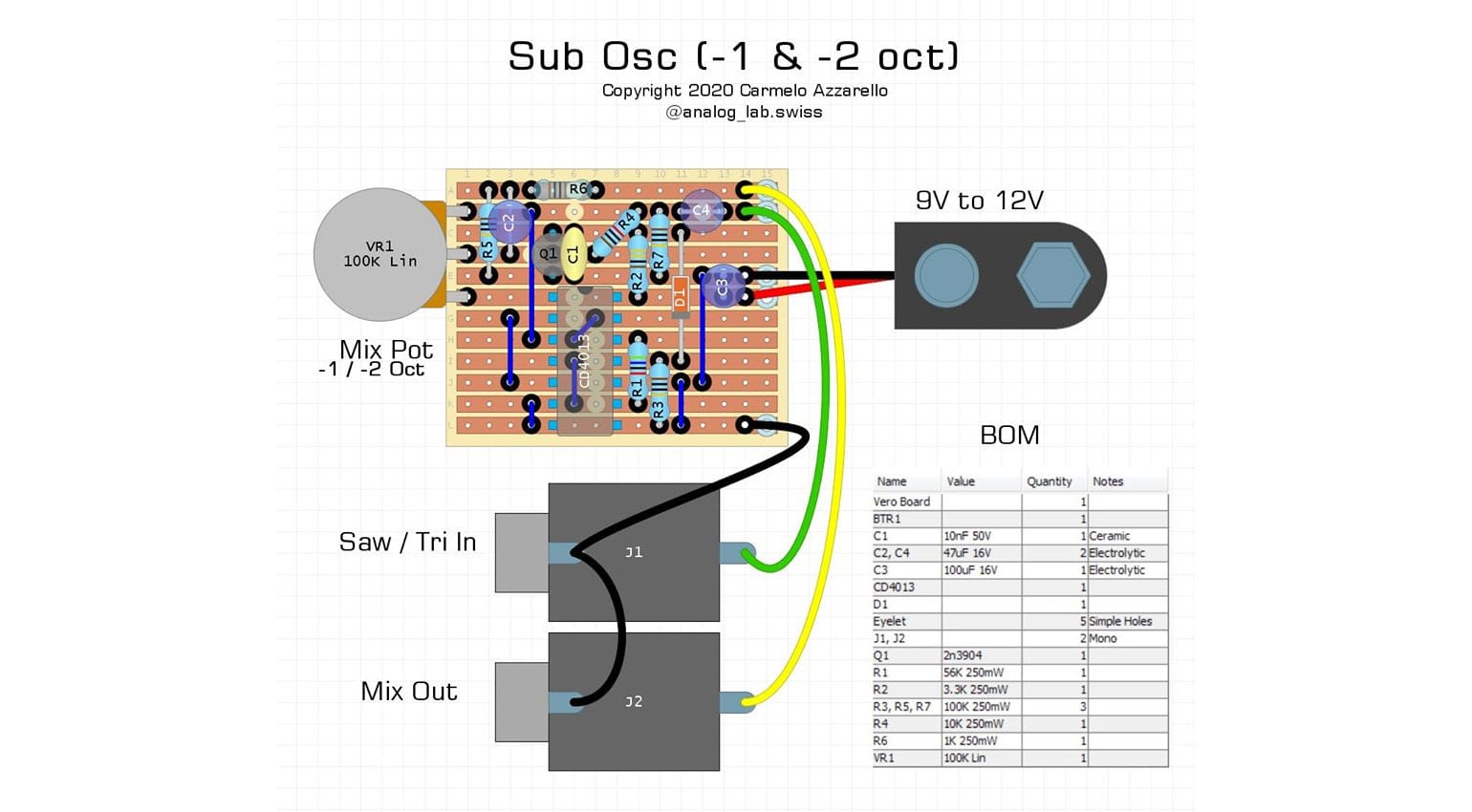
Here’s the schematic I used:
Ahhh ok. I was thinking they were both attempts to prevent negative voltage. On my breadboard setup I’m taking the outputs after two resistors like in the e-Druid schem, and it’s working good. If I don’t want to use it for gates/clock division, I should be good to leave it like this? Or should I throw in the diodes
Thanks Richard you are a great resource to us all!
Yeah, if you’re using those outputs for audio, leave 'em like that.
In stead of diodes you could choose for a potentiometer and get a mix of both square waves, which can result in a step shaped waveform. Furthermore you can gradually fade from one square to the other.
Carmelo thanks a lot for sharing this project.
I’ve found it very useful to enhance my Crave.
I’ve just built the V2 with clock divider outputs and it works good, but I’ve question for you about the clock dividers.
What can I feed with the clock divider outputs?
I’m looking forward to hearing from you
Cheers,
Massimo
You can send the output of the clock dividers to the crave by connecting them to the audio in of the crave. The externally applied signal will then replace the noise source of the crave. Next use the mix pot to fade between this audio and the oscillator of the crave or to mix them.
Thanks for your reply ![]()
I built one of these according to the original stripboard by Carmelo Azzarello. I considered it an easy build but am really puzzled that I could not get any sound from it, even though I even tried it on a crave exactly as in the original youtube video. Before I investigate further, am I right to see 10 cuts on the stripboard (A6, B6, B12, D4 and the rest under the IC) and 7 links?
Have you tried to probe the circuit using an amplifier? Have a look at this: Need some help with the kosmo vco w/ tuner. Please! I’ve lost weeks - #30 by Jos
It turns out that I misplaced the leg of a capacitor by one row. Works fine now! I find it helpful to just let go of a project and revisit it a few weeks later with a clear mind. I was able to spot the mistake immediately after revisiting it.
I’ve got some CD4013’s about to land in my mail box any day now and was planning to build a subOsc for my current project modifying Yamaha PS-3.
The architecture paraphonic with digital oscillator chip with mixed outputs (low and high bits) and no dedicated monophonic mode, so I’m starting to doubt if adding a subOsc is going to be useful or if it will just be a weird sound generator. Anyone tried something similar?
I would add that pins 4, 6, 8 and 10 should be grounded, not just 4 and 10.
Although it works the way it is, it is indeed wise to set those pins to gnd.
Hello, I built this using the WesleyV layout. The -1 octave sounds fine, but there is no -2 octave. I just get the -1 output. The blend output blends between-1 and slightly louder -1. I’m wondering if there needs to be a resistance between pins 2 and 5. Off to the breadboard!


