So I’ve decided I want to make my own Modular Synth, even if it’s just a super simple Square/Tri/Saw type thing. THing is, I’m really new to Schematics, Circuits, and Components. I am doing my research but I wanted to know if I was understanding this image properly.
I used EasyEDA to piece together my interpretation of the circuit, but I’m not sure if I got it right.
You got some connections misdirected here. RP1 connects to the same point as the junction of C1 and U1, not the transistor base (which connects to nothing, Sam recommends cutting it off). R2 also connects to that point, not to ground.
The part number shown for the transistor is… well, I don’t know what it is. But with a 9V supply you will want a transistor with a low avalanche voltage such as SS9018.
This oscillator can’t drive a bare 4-8Ω speaker, it has to be a powered speaker with built in amplifier (or a separate amplifier and speaker).
The original has an LED. You’ve drawn a rectifier diode, 1N4007. If you don’t want an LED lighting up you can just leave it out. It’ll affect the frequency of the oscillator but no diode is needed to make it work.
You should be aware that while this oscillator is very simple in terms of parts count, it is not necessarily simple to make it work. Even if you have a suitable transistor type such as SS9018 sometimes you have to try several different ones to find one that works. With 9 V power especially it can be a bit of a challenge. There are easier oscillators to get working, even if they have a couple more parts or an IC to deal with. I wrote more about this oscillator here Super Simple Oscillator: Simple except when it isn’t – Analog Output .
I’ve double checked everything, power runs through all components the way it should? Sadly don’t have any 10K pots lying around, and this is technically a different transistor. What would cause noise like this? To much/Too little voltage, Wrong transistor/Pot? Like I said, I’m still learning. I’m mostly a digital artist, so th ephysical realm is new to me.
First thing: DID YOU CUT OFF THE MIDDLE LEG, AND ARE YOU USING 2N3904 NPN TRANSISTORS?
The super simple oscillator def is finicky. You are basically exploiting a behavior of transistors such that they are breaking down (reverse avalanche). Save yourself some headache and make sure you only really try this with some transistors that have been known to “work” (technically break) at 9v.
Get yourself a bunch of 2N3904 NPN transistors. As was stated before, there isnt any guarantee that even the first 5 you test will work.
If you are curious about how the reverse avalanche stuff works, and some voltages needed for various transistors this site has proved useful:
Thank you, Caustic. I’ll look into all of this.! I appreciate your patience. Money is tight so I was seeing if I could use what I had in salvage to nake an oscillator. But it seems I may have to buy some stuff when I get paid.
(I did cut off the ‘base’ leg in all the various Trans I was using. I tried like 5 different ones. I eventually got the led flickering a bit more at 9 and 15 volts, but no sound on the new circuit config. Just typical amp static.
EDIT: I seem to have an AN7112 Amplifier chip. I’ve seen that Oscillation has something to do with phasing, and OScillators often have amplifiers set up with them, so is it possible to use this chip instead of trying to force a Transistor into Breakdown mode?
That’s an audio power amplifier chip, maybe there’s some way to turn it into an oscillator but I don’t know.
You didn’t say what transistor you’re trying to use. Many will require 18 V or so (you could use two 9 V batteries in series).
It also isn’t fully clear what the breadboard circuit is, as noted above the schematic has some errors though from what I can make out the breadboard looks at least closer to correct. One thing to note is that different transistors have different pinouts — with the flat side facing you and leads pointing down, some go EBC (emitter, base, collector left to right), some go CBE, and a few oddballs have yet another ordering. You’d have to check the transistor’s datasheet to find out what it is.
For a project more likely to work without fuss, you could try a Schmitt inverter oscillator
or for something a little more fun, an Atari Punk Console
You’ll need to buy some parts but only a couple bucks worth at worst.
I’ll give it a try once I can gather components. No local shops around here for such a thing, so I’ll have to peruse a decent budget source for things. I appreciate everyones help so far! But I think this is on hold for now.
Oh. Also because I mentioned it earlier, this is the pinout of the AN7112 amp chip I salvaged. I don’t 100% know what I’m looking at, but I did managed to actually wired it up to amplify audio… slightly. I have a lot to learn.
Any ideas if this pinout has the potential for any sort of Oscillator?
EDIT: One of the legs on my chip was broken, and just hadn’t fallen off (somehow). Explains why the the thing I salvaged it from wasn’t working right. lol
Speaking of which I was actually curious about something. I seen a lot of these circuit simulators online but I’m not sure which one is the most accurate.
I was using one last night to simulate a very simple blinking circuit for an LED, but despite the fact that my circuit was successful in the simulation, in actual practice it was not behaving the same way. Essentially meaning the LED wasn’t blinking at all.
I’m sure that I probably did something wrong but I’m wondering if there are any circuit simulators out there that are actually accurate to real life?
This is the blinking circuit I was working with. There was two different variations of this from two different YouTubers and I tried both of them and neither of them work.
The LED is always on. And connected to the “Transistor” portion of the Optocoupler (or switching portion), and the capacitor is supposed to charge itself and then release triggering what I’m assuming is a photoresistor which then shuts off the ground cinnection to the LED.
And based on the simulation this should work if I’m understanding it properly. But it seems that in person on a breadboard, the LED stays on indefinitely regardless of the size of capacitor.
I think i need to educate myself somehow.
The reason I’m asking about a stimulator is because I can’t really afford to constantly buy new components, and have them burn out on me if I’m doing something wrong. So having a stimulator would mean I could test some stuff out before wasting valuable components. Especially since most of my stuff is salvaged at the moment and I’m now running low on things.
Update! While I wait for things I ordered, I decided to screw around and I got squealing out of a speaker. It’s unclear whether that was oscillation, or 15 volts to a speaker makes it scream in pain?
needless to say the 100K resistor I used got really hot, so I thought it was smart to use a 500K potentiometer. And at the end of all of it I finally achieved the blue smoke.
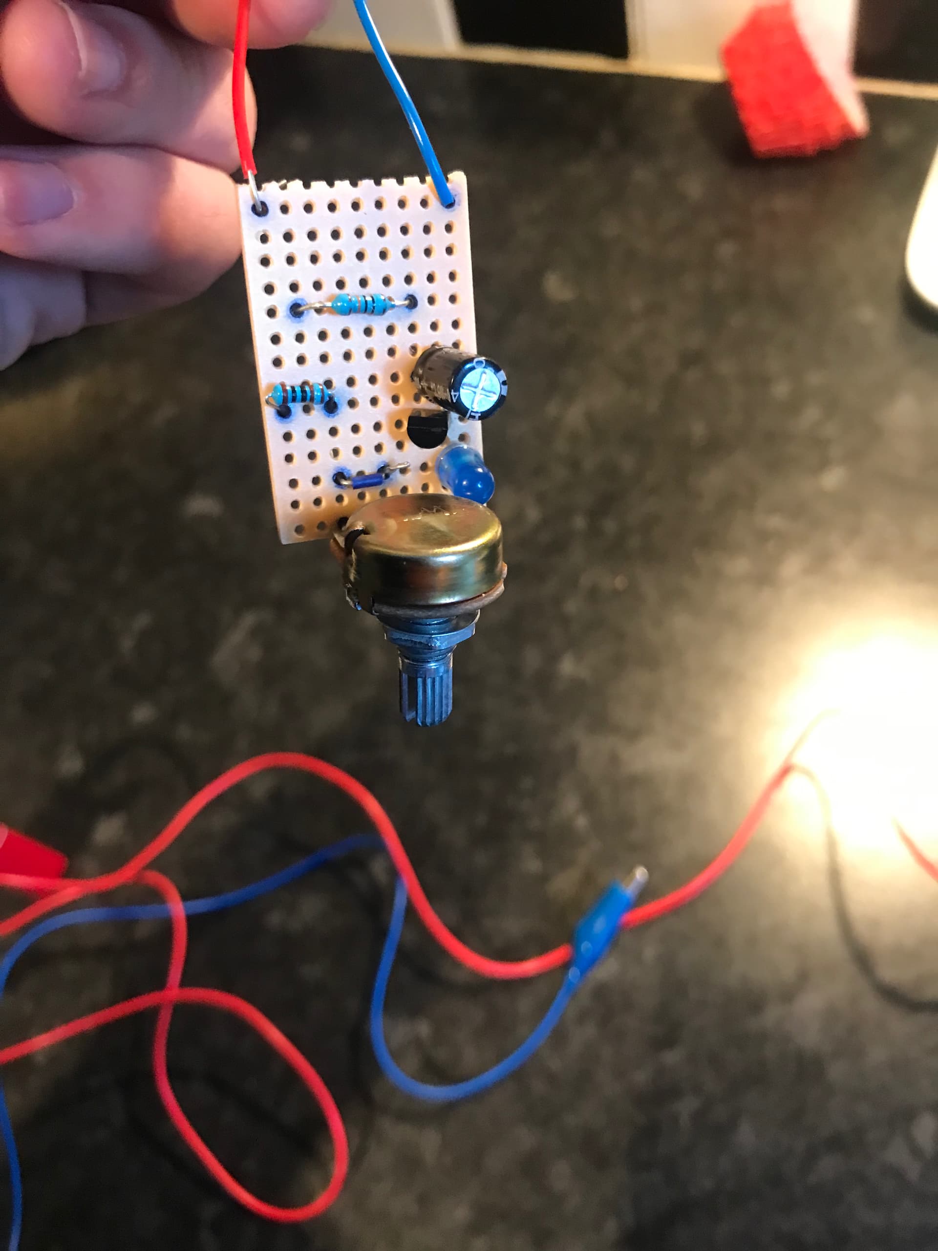
Thought I’d post my first project, I’m 100% a beginner in anything electrical. So for my first project, and I’m sure ya guessed it, the super simple oscillator. And it works! Miraculously.
Took a bit of fiddling around on the bread board but got there after a while. Transferred it on to strip board to learn how to solder. The soldering itself is a bit dodgy but it works. Don’t have a speaker to hook it up to so I’ve no idea how it sounds but the LED is oscillating.
Happy enough with the outcome!!
Thought I’d share cause I don’t know anyone personally that would actually care lol
Bravo! Now get yourself something to amplify and play it. Keep us posted, and know there are many here on the same journey and all progress is appreciated. Keep going.


