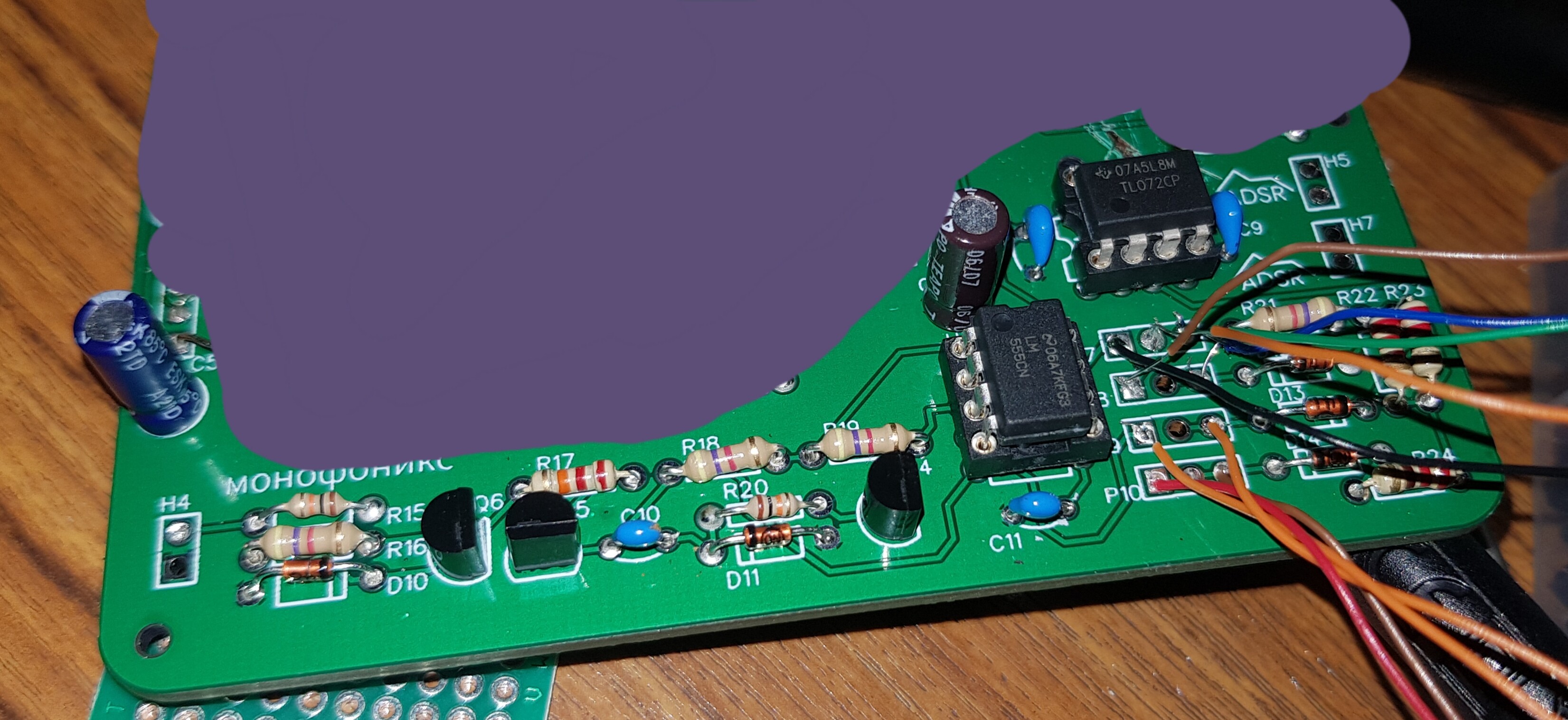
Hi everyone I’m really pissed off, I spent 3 hours trying to made this (image below) ADSR from Schmitbitz but it doesn’t work correctly. Even through I checked every components every connections the resistances of every resistors and all but no it doesn’t want to work correctly…
The problem is that when I put the decay at maximum the ADSR level goes to 11V without being triggered, and when I trigger it, it only goes to 5V or 4V. Maybe I should change the value of some components? I don’t know…
Maybe I should power the opamp with +12V and -12V?
Yeah I already checked that with my multimeter if my soldering were good and it was, verified every resistors, checked the schematic I made on KiCAD… Aaah omg I think maybe my 555 is bad, I mean it’s weird. Thanks dude but I think I’m doomed
Here’s a messy pic of my build and just showed the part that doesn’t work 20210116_211550|690x317
So your issue is with the decay at max makes the level go to 11v untriggered, and when triggered it drops voltage to 4-5v.
If i am reading this right, the 2.2M decay pot is connected in series with the 12k sustain pot. That is connected to the discharge pin, which simply routes through a transistor to ground. Since you get a voltage drop when you turn up your decay, this means that increasing the resistance there is causing the voltage drop before the inverting OpAmp stage.
I could be wrong, but if the diode connected to decay were inverted, i think this might explain why.
I posted that before i saw the image. the polarity looks fine. Right now, i would check the connection to the board below as well as the pots themselves. Make sure everything is grounded.
Yeah the pots are connected to the board and their values are fine, my soldering looks sketchy but the wires are soldered don’t worry. I also didn’t connect the center pin since we just use two wires on the pots except for the sustain.
My meter was broken… My 60€ meter was broken? When I set my supply to 12V it shows 8V and when I set my supply to 8V it shows 5V… So my adsr kinda works now. The only problem is that if I set the decay at maximum (or minimum i don’t know) it sets the output of the opamp at 12V. Plus the voltage of the ADSR drops even when I set the sustain at maximum
For example I set the sustain on its maximum level here so the voltage should stay linear but it’s dropping
i’m reviving this post because i’m dealing with the same circuit but i have a different problem.
i don’t have access to a scope so i’ll describe the workings of my ADSR after listening to it
A is adding a delay to the beginning of the sound from the positive edge of the gate
D is adding a volume slope to the attack of the sound (what i expected the A to do)
S is changing the sustain level, the peak volume and the release time
R does nothing
There’s a loud click sound at the positive edge of the gate And sometimes it happens on the negative edge
Also there’s always a residual volume after the negative edge Even with the release at minimum
I don’t see any discrepancies between your schematic and Schmitz’s, at least for the ADSR part.
I do see you’re using an NE555P. This isn’t quite equivalent to the ICM7555. I recommend trying the latter, see if that improves performance. If not then presumably there’s some error in the PCB layout or assembly.
This is presumably the known behavior that’s been discussed here before, a characteristic of this circuit and similar ones. Basically the problem is that the release voltage can’t get to 0 V other than very slowly once it’s dropped low enough compared to the diode forward voltage. There’s a design from Kassutronics that mostly avoids the problem by using op amps with the diodes to make precision rectifiers:
(there’s still a small amount of offset left due to transistor resistance, and there’s at least one design that supposedly fixes that by using MOSFETs, but it’s a much smaller problem.) I did a Kosmo version of the Kassutronics ADSR and it works well.


