I used tip and ring, it means you only have one cable running from the controller to the synth rather than two. Then at the synth I have a TRS → 2xTS converter:
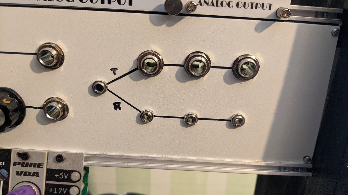
(OK, TRS → 3x(2xTS) …)
I used tip and ring, it means you only have one cable running from the controller to the synth rather than two. Then at the synth I have a TRS → 2xTS converter:
(OK, TRS → 3x(2xTS) …)
Thanks @eric & @analogoutput 
Can i use a Nano instead of a Micro with no change in the code ?
(with a check on the correspond pins of course)
I believe so ![]()
There is something that i don’t understand somewhere …
On the Audette code explaination, i can read that :
Physical Setup, Ribbon:
Top of Soft Pot: (No Connection)
Wiper of Soft Pot: A5
Bottom of Soft Pot: Gnd
It don’t need +5V on the Top like this ?
No, because it’s using the internal pullup resistor.
Ok, thanks again
(more …)
I try to download the code, and i have some problem.
I download the Biquad.h, test the code and i have some errors
" Arduino : 1.8.9 (Windows 7), Carte : “Arduino Nano, ATmega328P (Old Bootloader)”
sketch_may04a:746:5: error: stray ‘\302’ in program
 © 2021 GitHub, Inc.

 ^
sketch_may04a:746:5: error: stray ‘\251’ in program
sketch_may04a:11:1: error: ‘Skip’ does not name a type
Skip to content
^
In file included from C:\Users\Client\sketchbook\libraries\sketch_may04a\sketch_may04a.ino:81:0:
C:\Program Files\Arduino\hardware\arduino\avr\libraries\SPI\src/SPI.h:178:39: error: ‘SPISettings’ has not been declared
inline static void beginTransaction(SPISettings settings) {
^C:\Program Files\Arduino\hardware\arduino\avr\libraries\SPI\src/SPI.h: In static member function ‘static void SPIClass::beginTransaction(int)’:
C:\Program Files\Arduino\hardware\arduino\avr\libraries\SPI\src/SPI.h:203:21: error: request for member ‘spcr’ in ‘settings’, which is of non-class type ‘int’
 SPCR = settings.spcr;

                 ^
C:\Program Files\Arduino\hardware\arduino\avr\libraries\SPI\src/SPI.h:204:21: error: request for member ‘spsr’ in ‘settings’, which is of non-class type ‘int’
 SPSR = settings.spsr;

                 ^
C:\Users\Client\sketchbook\libraries\sketch_may04a\sketch_may04a.ino: In function ‘void setup()’:
sketch_may04a:217:6: error: redefinition of ‘void setup()’
void setup() {
^C:\Users\Client\sketchbook\libraries\sketch_may04a\sketch_may04a.ino:1:6: note: ‘void setup()’ previously defined here
void setup() {
^sketch_may04a:98:19: error: ‘Serial1’ was not declared in this scope
#define Serial_t (Serial1) //for MIDI for Arduino Micro or for TEENSY
^C:\Users\Client\sketchbook\libraries\sketch_may04a\sketch_may04a.ino:241:19: note: in expansion of macro ‘Serial_t’
if (WRITE_MIDI) Serial_t.begin(31250);
^C:\Users\Client\sketchbook\libraries\sketch_may04a\sketch_may04a.ino: In function ‘void loop()’:
sketch_may04a:267:6: error: redefinition of ‘void loop()’
void loop() {
^C:\Users\Client\sketchbook\libraries\sketch_may04a\sketch_may04a.ino:6:6: note: ‘void loop()’ previously defined here
void loop() {
^C:\Users\Client\sketchbook\libraries\sketch_may04a\sketch_may04a.ino: In function ‘void setBendRange(int)’:
sketch_may04a:98:19: error: ‘Serial1’ was not declared in this scope
#define Serial_t (Serial1) //for MIDI for Arduino Micro or for TEENSY
^C:\Users\Client\sketchbook\libraries\sketch_may04a\sketch_may04a.ino:601:3: note: in expansion of macro ‘Serial_t’
Serial_t.write(CC_byte); //control change
^
C:\Users\Client\sketchbook\libraries\sketch_may04a\sketch_may04a.ino: In function ‘void transmitBrightness(byte)’:
sketch_may04a:98:19: error: ‘Serial1’ was not declared in this scope
#define Serial_t (Serial1) //for MIDI for Arduino Micro or for TEENSY
^C:\Users\Client\sketchbook\libraries\sketch_may04a\sketch_may04a.ino:625:3: note: in expansion of macro ‘Serial_t’
Serial_t.write((byte)MIDI_CC);
^
C:\Users\Client\sketchbook\libraries\sketch_may04a\sketch_may04a.ino: In function ‘void transmitPitchBend()’:
sketch_may04a:98:19: error: ‘Serial1’ was not declared in this scope
#define Serial_t (Serial1) //for MIDI for Arduino Micro or for TEENSY
^C:\Users\Client\sketchbook\libraries\sketch_may04a\sketch_may04a.ino:648:5: note: in expansion of macro ‘Serial_t’
 Serial_t.write((byte)MIDI_PITCH_BEND);

 ^
C:\Users\Client\sketchbook\libraries\sketch_may04a\sketch_may04a.ino: In function ‘void recenterMidiPitchBend()’:
sketch_may04a:98:19: error: ‘Serial1’ was not declared in this scope
#define Serial_t (Serial1) //for MIDI for Arduino Micro or for TEENSY
^C:\Users\Client\sketchbook\libraries\sketch_may04a\sketch_may04a.ino:657:3: note: in expansion of macro ‘Serial_t’
Serial_t.write((byte)MIDI_PITCH_BEND);
^
C:\Users\Client\sketchbook\libraries\sketch_may04a\sketch_may04a.ino: At global scope:
sketch_may04a:746:8: error: expected unqualified-id before numeric constant
 © 2021 GitHub, Inc.

    ^
exit status 1
stray ‘\302’ in program
and i understand nothing ![]() what can i do ?
what can i do ?
please some help
No idea about the rest, but the “stray” complaints are due to the compiler (either gcc or if it’s some arduino thing) choking on non-ASCII characters, which either means that it doesn’t handle non-ASCII at all, or that it expects the files to use UTF-8 but got Latin 1 or Windows encoding.
sketch_may04a:746:5: error: stray ‘\302’ in program
Upgrading to a more recent version may fix this.
thx i 'll go try it
(…)
yes now this one has disappeared
Well i solved the code problem (thanks @eric), but the circuit does not work.
I tested and I have 5V at the regulator, at the + of the arduino and at the + of the IC.
The arduino also sends 5V in the ribbon which works.
I also have 5V in Gate output, but nothing in CV and VCF output.
Infact nothing on the out of the MCP4922
@analogoutput have you an idea of what I could have done wrong
So you’re saying you have correct voltages coming from the ribbon to the Arduino, but nothing coming out of the DAC?
You have +5 V on the DAC Vref inputs?
You have correct pin assignments in the code for the signals to the DAC?
yes
yes 5V on Vref A & B
i think, i do that
I change that in the code because there was an error with Serial1
Before :
#define Serial_t (Serial1) //for MIDI for Arduino Micro or for TEENSY
//#define Serial_t (Serial) //for MIDI for Arduino UNO
After :
//#define Serial_t (Serial1) //for MIDI for Arduino Micro or for TEENSY
#define Serial_t (Serial) //for MIDI for Arduino UNO
and some mod find in your blog decription (Ribbon part 3 software change).
to invert the gate signal out, can i do this ? :
Before
#define TRIG_NOTE_ON (0) // LOW
#define TRIG_NOTE_OFF (MAX_DAC_COUNTS) //HIGH
After
#define TRIG_NOTE_OFF (0) // LOW
#define TRIG_NOTE_ON (MAX_DAC_COUNTS) //HIGH
or that ?
#define TRIG_NOTE_ON (0) // HIGH
#define TRIG_NOTE_OFF (MAX_DAC_COUNTS) //LOW
thanks
Here’s the comparison of my code to Audette’s, annotated.
Apparently I had to change angle brackets to quotes to make this work
    31c26
    < #include <Biquad.h>   //http://www.earlevel.com/main/2012/11/26/biquad-c-source-code/
    ---
    > #include "Biquad.h"   //http://www.earlevel.com/main/2012/11/26/biquad-c-source-code/

For Nano or Pro Mini use Serial, not Serial1
    47,48c42,43
    < #define Serial_t (Serial1)  //for MIDI for Arduino Micro or for TEENSY
    < //#define Serial_t (Serial) //for MIDI for Arduino UNO
    ---
    > //#define Serial_t (Serial1)  //for MIDI for Arduino Micro or for TEENSY
    > #define Serial_t (Serial) //for MIDI for Arduino UNO

Apparently I used a different analog pin
    52c46
    < const int ribbonPin = A5;
    ---
    > const int ribbonPin = A3;

These are unused lines I deleted
    55,59d48
    < //int drivePin = 4; //Digital pin #4
    < //int drivePin_state = HIGH;
    < const int pushButton1_pin = 2;   // Push button, Digital Pin
    < const int pushButton2_pin = 3;   // Push button, Digital Pin
    < const int pushButton3_pin = 4;   // Push button, Digital Pin
    64,65d52
    < //const int comparePin = A4;
    < //const int comparePinGnd = A5;
    90,92d76
    < #define RIBBON_BY_VCC 1
    < #define RIBBON_BY_WIPER 2
    < const int ribbon_mode = RIBBON_BY_WIPER;
    96c80

Different values observed in hardware
    < int ribbon_max_val = 335,ribbon_min_val = 15; //for my Arduino Micro
    ---
    > int ribbon_max_val = 378,ribbon_min_val = 20; //for my Arduino Pro Mini
    107c91

I made it span a wider pitch range
    < const float ribbon_span_half_steps_float = 36;
    ---
    > const float ribbon_span_half_steps_float = 60;

I changed the bottom note
    137c121,122
    < #define CV_note_bottom (12)  //Note C1 instead of C0
    ---
    > //#define CV_note_bottom (12)  //Note C1 instead of C0
    > #define CV_note_bottom (0)  //RSH no offset

More constants based on what is seen in hardware
    140c125
    < #define MAX_DAC_VOLT (5.180)   //laptop is 5.04V, USB wall-wart is 5.182V
    ---
    > #define MAX_DAC_VOLT (4.97)   //laptop is 5.04V, USB wall-wart is 5.182V

This is a little mysterious – I *think* Audette's synth uses gates
that are the reverse of Euro/Kosmo?

    142,143c127,128
    < #define TRIG_NOTE_ON (0)     // LOW
    < #define TRIG_NOTE_OFF (MAX_DAC_COUNTS) //HIGH
    ---
    > #define TRIG_NOTE_OFF (0)     // LOW
    > #define TRIG_NOTE_ON (MAX_DAC_COUNTS) //HIGH

Needed to make serial monitor debugging work
    189c173,174
    <   Serial.begin(115200*2);  //for Arduino Micro only
    ---
    >   //  Serial.begin(115200*2);  //for Arduino Micro only
    >   Serial.begin(9600);  // RSH

More unused lines I deleted
    241d225
    < int prev_but_val[] = {HIGH, HIGH, HIGH};
    303,308d286
    <
    <   //read putshbutton
    <   boolean but_val = (digitalRead(pushButton1_pin) == LOW);  //pressed makes it LOW...so set the value as TRUE
    <   boolean but2_val = (digitalRead(pushButton2_pin) == LOW); //pressed makes it LOW...so set the value as TRUE
    <   //boolean but3_val = (digitalRead(pushButton3_pin) == LOW); //pressed makes it LOW...so set the value as TRUE
    <
    395,396d372
    <   prev_but_val[0] = but_val;
    <   prev_but_val[1] = but2_val;
    412d387
    <   //if (drivePin_state == LOW) ribbon_value_float = RIBBON_SPAN - ribbon_value_float;
    414,421d388
    < //  //invert the drive pin
    < //  toggle_counter++;
    < //  if (toggle_counter >= 1) {
    < //    toggle_counter = 0;
    < //    drivePin_state = !drivePin_state;
    < //    digitalWrite(drivePin,drivePin_state);
    < //  }
    <
    641c608

I changed this so both CV outputs are the same
    <   const float KBD_track = 0.6;
    ---
> const float KBD_track = 1.0; // RSH: No difference in scalingThanks a lot !!!
i will try this tomorrow 
for this one you add a ligne ?
Correct, but // is a C++ comment so that line is ignored by the compiler. If you’re updating things by hand, you can just change (12) to (0).
(or try it without that change and only change the lowest note setting once you’ve gotten things to work and figured out what note you want)
Thx @fredrik
i’ve just test it and the same thing, still nothing out of the DAC 
Are there several kinds of MCP4922 and I will not have the right one?
mine is: MCP4922 E / P
or maybe is it defective (how can I test it plz)
Or can it come from my DIY ribbon with copper and velostat ?
I think you could try to test the ribbon controller and the dac separately. Just write a simple sketch that reads pin A5 and prints it to the serial out. And then write a sketch that outputs just a sequence of voltages at the dac. I will see if I can come up with something usable during my lunch break
edit: For the analog read (check if the diy ribbon works):
void setup() {
  // initialize serial
  Serial.begin(9600);
}

void loop() {
  // read pin
  int val = analogRead(A5);
  // Convert the analog reading (which goes from 0 - 1023) to a voltage (0 - 5V):
  float voltage = val * (5.0 / 1023.0);
  // print on serial
  Serial.println(voltage);
}
run this on the arduino and then check the serial monitor
edit2: For the dac test you can use parts of the audette code:
#include <SPI.h>

const int slaveSelectPin = 10;  //for commanding the DAC
const int trig_pin = 5;  //for Trigger High/Low for CV

void setup() {
  //initialize the DAC
  pinMode(trig_pin,OUTPUT); digitalWrite(trig_pin, 1);
  pinMode(slaveSelectPin, OUTPUT);
  digitalWrite(slaveSelectPin,HIGH);  //set DAC ready to accept commands
  SPI.begin();
  SPI.setDataMode(SPI_MODE0); //MCP4922 can be either Mode 0 or Mode 3 (supposedly)
  SPI.setBitOrder(MSBFIRST);
}

void loop() {
  // setting the two DAC channels to
  MCP4922_write(slaveSelectPin,2000,4000);
  digitalWrite(trig_pin, 0); // could also be 1, not sure here
}


void MCP4922_write(const int &slavePin,const int &value1,const int &value2) {
  int value = 0;
  byte configByte = 0;
  byte data=0;
  int channel=0;

  for (channel = 0; channel < 2; channel++) {
    digitalWrite(slavePin,LOW);  //set DAC ready to accept commands
    if (channel == 0) {
      configByte = B01110000; //channel 0, Vref buffered, Gain of 1x, Active Mode
      value = value1;
    } else {
      configByte = B11110000; //channel 1, Vref buffered, Gain of 1x, Active Mode
      value = value2;
    }

    //write first byte
    data = highByte(value);
    data = B00001111 & data;  //clear out the 4 command bits
    data = configByte | data;  //set the first four command bits
    SPI.transfer(data);

    //write second byte
    data = lowByte(value);
    SPI.transfer(data);

    //close the transfer
    digitalWrite(slavePin,HIGH);  //set DAC ready to accept commands
  }
}
This should set your DAC channels to ~2.5V and ~5V which you can check with your multimeter
edit3:
Only now spotted it: there is some debugging code just set these to one (line 34ff) and then look at the serial monitor:
//debugging info
#define PRINT_TEXT (0)
#define PRINT_BEND_TEXT (0)
#define PRINT_CAL_TEXT (0)
#define PRINT_RAW_RIBBON_VALUE (0)
#define PRINT_CV_TEXT (0)

