Woop Woop i got the code compiled and uploaded to my Teensy 3.2 =) (thanks to @moly_wan for the nudge)
just started to work on the board hookups and im a bit lost.
None of the inputs or pots are labelled that i can see.
what i have noted is:
MIDI In - D0
Gate In - D2
Gate In - D3
Gate in - D4
PWM Led K- D9
PWM Led H - D10
CV In - A9_D23
CV In - A8_D22
CV In - A7_D21
Pot - A6_D20
Pot - A5_D19
Pot - A4_A18
Pot - A3_D17
Pot - A2_D16
Pot - A1_D15
Pot - A0_D14
TL072(Pin3) - A14_DAC
PWM Led S - D25
CV In - D28_A17
CV In - A20_D31
CV In - SDA1_A19_D30
CV In - A18_SCL1_D29
But the Gate In, CV In and Pots dont have clear labels and i cant see anything in the code.
Is it something that matters? I dont want to spend time soldering only to have the Snare CV In control something random XD
Part of me assumes that they will go like: Kick Gate In - D2, Hat Gate In - D3… etc
but id rather not waste time doing it wrong haha!
Amazing!! thank you!! its been a bit of a mission for me this one. im not really versed in Arduino/Teensy IDE stuff and this has been on my list of modules i wanted to make for ages =D
Ive got all my wires and stuff ready to go, really wanted to get this done right first time rather than risk messing it up and getting sick of it haha!
Thanks again for the help on this one!
ill post it up when its done XD
I wasnt so lucky with mine haha! made a few mistakes (soldered the 6 pitch and decay jack tips to the Teensy rather than from the resistors)
I didnt even see the T3.2 led come on… guess i have to check the +5v trace
id love to see a pic of yours if you took any =)
did you work from Otems Schematic or my stripboard layout? perhaps ive just been dumb and done something stupid on the board =/
Hi!
If you don’t have any LEDs on, none of the gates is trig. There is no flashing on startup, as there are times.
I based myself on Otem’s diagram, my brain has trouble doing veroboard gymnastics.
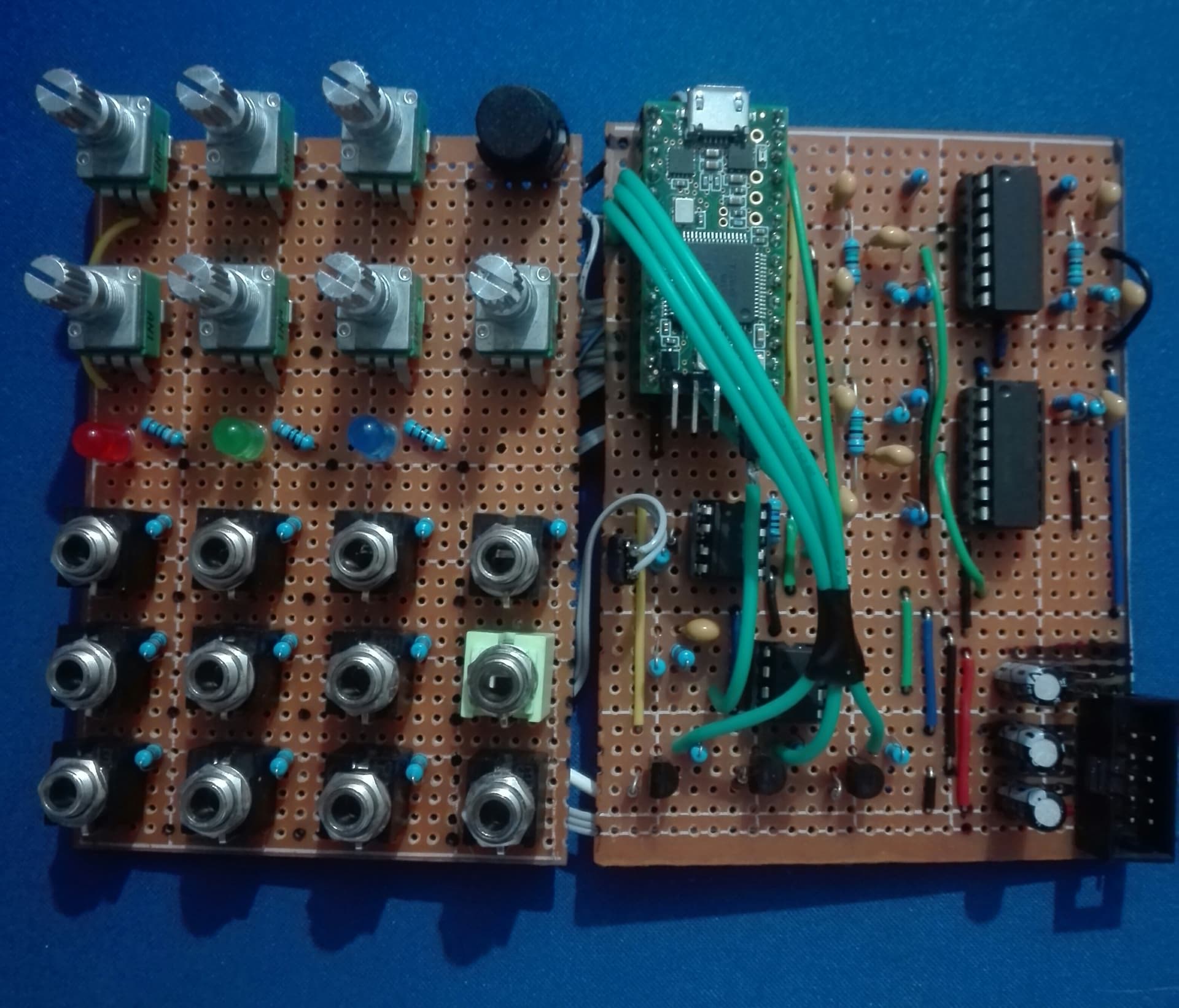
I took pictures before assembly but I’m not sure that helps you. I made a diagram that may be more useful to you.
Keep it up!
Last night i had noted a few things id done wrong.
Had a short from button to pots signal (fixed)
Soldered the 7 CV jacks wrong (fixed)
Soldered the Gate Trigs in the wrong place (Fixed)
But still no dice, so i decided to test the +5v from my PSU.
When the module isnt plugged in my PSU shows +5v but when i plug it in it goes to 0.5v and slowly drains down.
i thought it could be that the input for the +5v isnt grounded so i added a ground link and still does the same thing.
(makes me wonder if the BigButton I made is doing the same thing)
Ill have a good look at your schem and compare, first thing ive noticed is you have more E Caps than i do… I swear i only saw 3 on Otems schem
Another thing is you use more of the T3.2s GND connections than i do. Im just using GNDb. Is it necessary to use the others?
I use 2 more ecaps instead of the non-polarized 10uf at the tl072. it’s a diy bipolar with two 22uf, connected negative to negative. It works fine like that
I do my 5v on the board with L7805.
Do you have a FCPower type power supply with a small 78l05? I have one and I have a similar problem with a module too greedy in 5v.
It shouldn’t be a problem to use one ground rather than another, I use 2 to have 1 wire less.
I was confused by what looked like a +5 V input on the right, I’ll ignore that.
Looks like you have the pinout backward:
With the tab toward the left, +12 V goes to the bottom pin (input) and +5 V comes from the top pin (output).
You don’t need the 10u cap on the output side. You already have that on the +12 V. The datasheet does recommend a 330 nF cap (Mylar film is good) between the input pin and ground.
Ahh right, ty. I was looking at molys schem symbol. Would be double checking when making any ways.
Ill do another sketch when I get in, just out shopping at the moment haha.
@moly_wan Is there any reason you chose the L7805 rather than a 78l05?
Also been having a better look at my board and there’s definitely a short somewhere between the +5v and GND, i just cant find the thing haha.
so that would be why theres some iffy behaviour on my readings. shrugs
Hi @willow2x,
I looked at the teensy 3.2 specs and it only draws 45ma at 90mhz, with 3 extra leds. It must be able to be fed with a small 78l05.
What resistance are you seeing between 5v and ground?
Here I have a modified schematic of this teensy. I only want 3 knobs (CV inputs) for my design. Also, I want to take out the midi. Please leave any comments below.
You are missing a resistor+capacitor from U1 pin 6 to ground.
Op amp power connections make no sense. On U1 they should be to ±12 V, on U2 to +5 V and ground. On U2 there also should be a 100 nF cap from +5 V to ground; on U1 those bypass caps are already there (in the Power Connection section).
R1 and R6 both should be 100k, not 1k.
R9 is described as both 1k and 10k, should be 10k.
Power connections to and from Teensy are missing.
Power header is reversed, -12 V (which you have mislabeled +12 V) should be pins 1–2 and +12 V should be pins 9–10. Pins 1, 3, 7, 9 should connect to pins 2, 4, 8, 10.
What is your 5 V power source?
How are you planning to build this? Stripboard, self made PCB, fabbed PCB, what? If the latter, you are showing SMD parts, is that what you intend to use?
This has been sat in my “get to it later” draw for 2 years now… Knowing it had a short at 5v to GND.
took a bit of a break to build other things and get into ESP32/8266 etc…
And i thought sure ill give this another go after chatting with my bro about it.
Having to refresh myself on my schem as i went through to see if i had mis wired anything wasnt to fun (always thinking how i could do the wiring better…)
considering a rebuild or fresh build of moly_wans board…
One thing i found is that i put the 2n222A in the wrong way (simple fix, just spin em round)
but, i fixed my short on a whim. all it took was…
RUNNING A KNIFE AROUNDS ALL TRACES!!
wasnt expecting it to work, but hey bullshitery happens haha!!
going to fix the 2n222 tomorrow and give it a test. Legit cant believe thats all it took. just scrape the board with pointy thing.
I fixed it and also fixed the bit I found in the video too.
Next up is sort out a face plate for it!!
Finally verified it! I’m sure I can wire the grounds better but IT WOOOOORRRRKS!!