I am making a utility module containing a small oscilloscope. The oscilloscope was working properly when power was applied via a micro USB charger connected to the micro USB socket on board. However, when I connected the V+ and GND with wires to my 5V power source (Eurorack power bus -> connector -> PCB with 5V voltage regulator, as the scope needs 3.7V to 6V), the oscilloscope only works when my hand is within several centimeters of the module. What could be the problem?
Ofcourse I searched the internet, but I was not able to find anything applicable, as I am having trouble describing my issue in a couple of words.
It is not immediately clear to me at least what you mean by that. There should not be much of a difference when connecting the oscilloscope to its own or to a eurorack power supply. Unless you are doing specific measurements on the power supply of the euro rack or something similar.
So, is there any input signal connected to the oscilloscope? Does it start up at all and how do you know? Is there anything visible on the screen? Can you post a picture of your setup?
The oscilloscope screen is starting up when I have my hand near the module. As soon as I retract my hand it is powered down. When I get my hand within 5 cm of the module, the oscilloscope screen is starting up again. Could it be a grounding issue?
By now it is to dark to take any photos. I will post a picture of my setup tomorrow.
I assume that you checked your wiring and that you tested the circuit without anything connected to it?
Some regulators need capacitors right at the output, especially when the load is low (which doesn’t seem to be the case here…). Try adding a 100nF ceramic/film cap.
Do you mean the signal trace on the screen disappears or the whole device looses power?
When using an oscilloscope you need to connect 2 leads to the circuit you are measuring some signal in. One of the leads is a gnd wire the other a signal wire.
If you forget to connect the gnd wire, you often see a wildly varying signal that is all over the screen ( depending on some of the scope’s settings ). The signal is caused by the elektro magnetic field radiated by the wiring of the mains in your house/room (50 or 60 Hz, depending on the mains frequency in your country).
I can imagine that if the sensitivity of the scope is turned up very high, the scope will pick up a signal depending on holding your hands near the device ( actually near the input wire or input connector if there is no cable connected to it ). And the trace on the screen may disappear depending on the trigger setting of the scope. But for you to be able to “switch” the device on or off depending on how close your hand is to it, is very unlikely.
A more precise description of what is happening will clarify things, I think.
Could it simply be a trigger issue?
The scope may just look dead because it is not triggering.
When your hand gets close enough, some noise is induced and causes the scope to trigger and show a signal.
Try setting the trigger to automatic or make sure it has a signal it can trigger on and that the trigger settings allow it to trigger.
That’s what I thought as well. It is very improbable that the device switches off when a hand is held close to it. But let’s not ruling out latent telekinesis here…
Maybe we should ask @SynthesiS straight out: do object sometimes move around you without you touching them? Does stuff when it drops always miraculously fall into your hands?
Check the 5V regulator. Which one are you using? How do you have it wired? Are there capacitors connected to it, per the datasheet for the regulator? Are all those connections good?
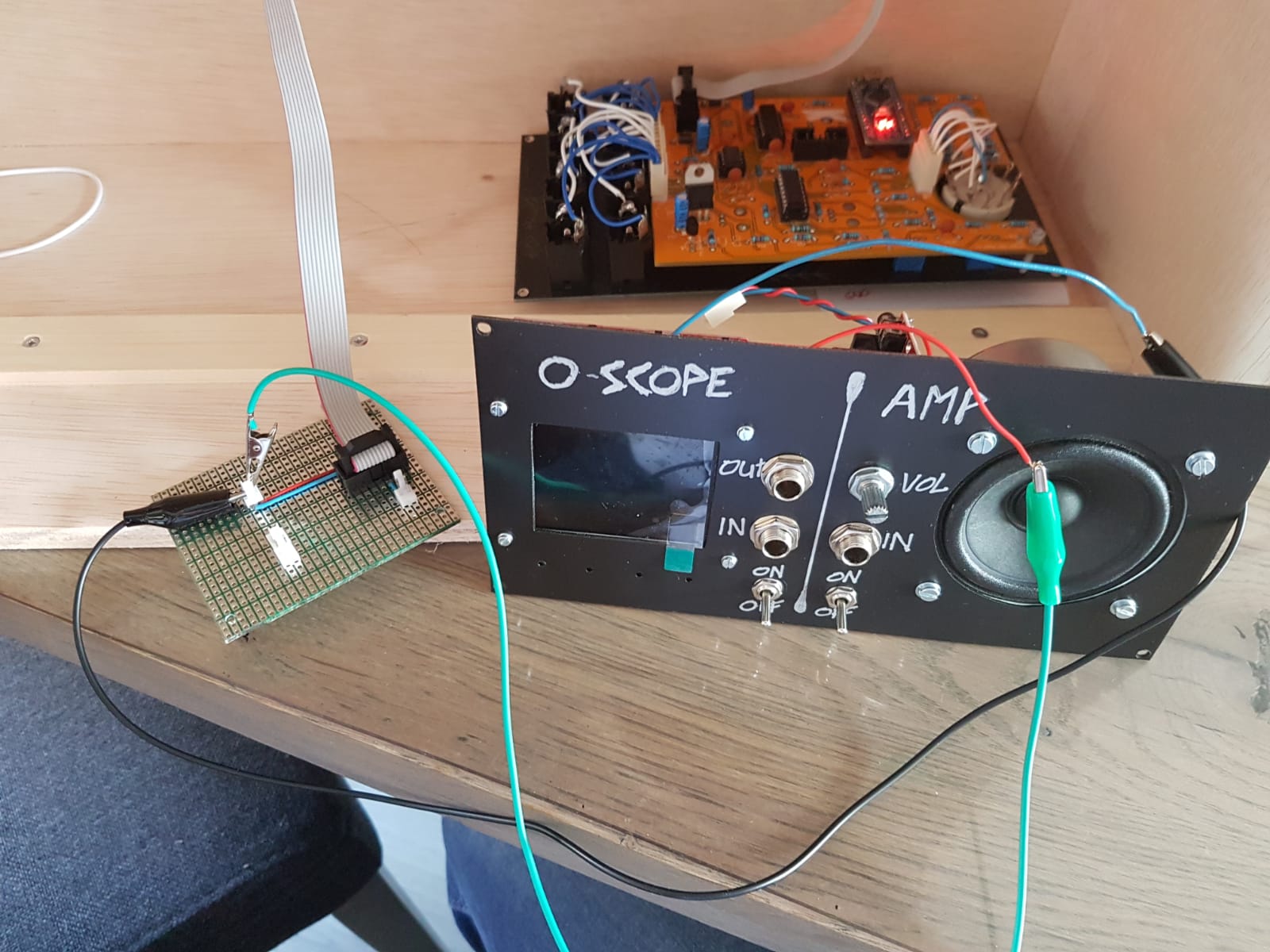
As you can see, I made a pcb which contains a 7805 voltage regulator (hidden behind Eurorack cable) to give me 5V that is now transferred via crocodile clamps to the oscilloscope wires.
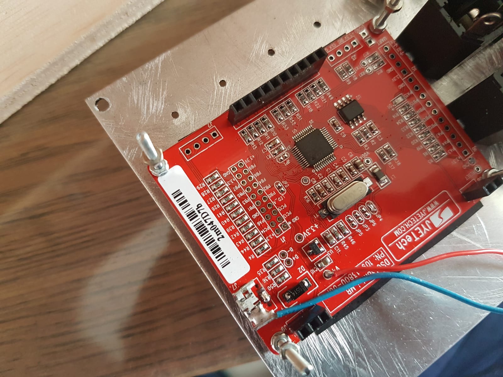
Back of panel picture, with top pcb of oscilloscope removed:
On the bottom left there used to be a USB micro port that was used to power the oscilloscope. As I did not have enough room to plug in a USB, I cut off the port and tried soldering wires to the remains of the 1st and 5th leads of the port. However, the leads were too small, so instead I soldered the positive wire to the V+ hole visible in the photo, and the ground wire to casing of the USB port.
The oscilloscope is able to power up when I have my hand touching (or close to) the panel.
However, when I pull my hand away from the panel, the oscilloscope loses power.
Do I have a grounding issue? Any suggestions on where to connect the ground wire on the oscilloscope?
PS: The oscilloscope has a battery connection port on the upper panel (removed in the second photo), but that is not working… Hooking the wires to that battery port does nothing…
I checked the output of the voltage regulator, which gives a nice 5V. I checked with a multimeter at both ends of the crocodile clamps visible in the second photo of my previous post.
It’s the scope panel you have to get near, and not the board with the regulator, is that right?
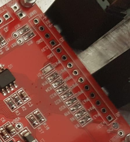
One would think the USB housing would be a good ground point. However there also appear to be three pads labeled GND on the right side:
and two toward the left:
You could try moving the ground connection to one of them.
Have you looked at this?
In particular there are some voltage measurement points shown on p. 2.
It looks as though there are two recommended ways to power the scope, via USB or battery. Putting 5V on the V+ pad isn’t mentioned as a valid way to do it and maybe it’s not sufficient. Maybe you should focus on getting the battery connection to work.
When I built the scope and powered it via USB micro, I checked the voltage measurements mentioned in the user manual, which are similar to the troubleshooting guide, and they checked out.
The battery connector is oddly enough not on the same board as the USB port, but on the board containing all electrical components. For some reason, attaching wires to the battery connector did not do anything, even though I soldered jumper J4 closed in accordance with the manual. Therefore, I just poked wires at V+ holes, and got it working; momentarily that is, with my hand close
Based on your suggestions, I will look at the battery connector a bit closer. Maybe a bad soldering connection??
This is in line with a USB micro data sheet I found online. Based on that data sheet, leads 1 and 5 were for power and ground (forgot which order).
Any idea why the scope did power up after connecting the 5V wire to V+, and the 0V/GND wire to the USB micro housing? With my hand near the panel, that is…
I have not tried measuring the 5V regulator when the scope was powered up yet. I will try this later today!
I am somewhat confused by your remark: or move your 0V wire to GND. As a total noob in electronics, could you elaborate on what you mean by that? To me, GND = 0V…
Thanks for your patience with me! I am an experienced scale model builder and model railroader, but am totally new to electronics…
Ach sorry I was unclear… I meant that if the USB shielding (where your blue wire is connected (that’s the one I called 0V wire)) is not connected to the internal ground (as fredrik suggested), then move that wire to a ground pad (GND).
You seem to ‘hold’ the panel in the picture. What is it you are touching here? There is no current of significance passing through your hand (the voltages are too low), so your hand pressure must by accident be making/breaking some connection that cases the scope to work / stop working.
Mind you that a visibly nice looking soldering connection may not be a good connection, so you may want to check those.
As for the +5 V point, that may be a point where you can measure 5 V when everything is connected correctly but not the point where you should connect the 5 V power supply.
Try to find the +V point as described in the trouble shooting manual mentioned by analogoutput.


 I am an experienced scale model builder and model railroader, but am totally new to electronics…