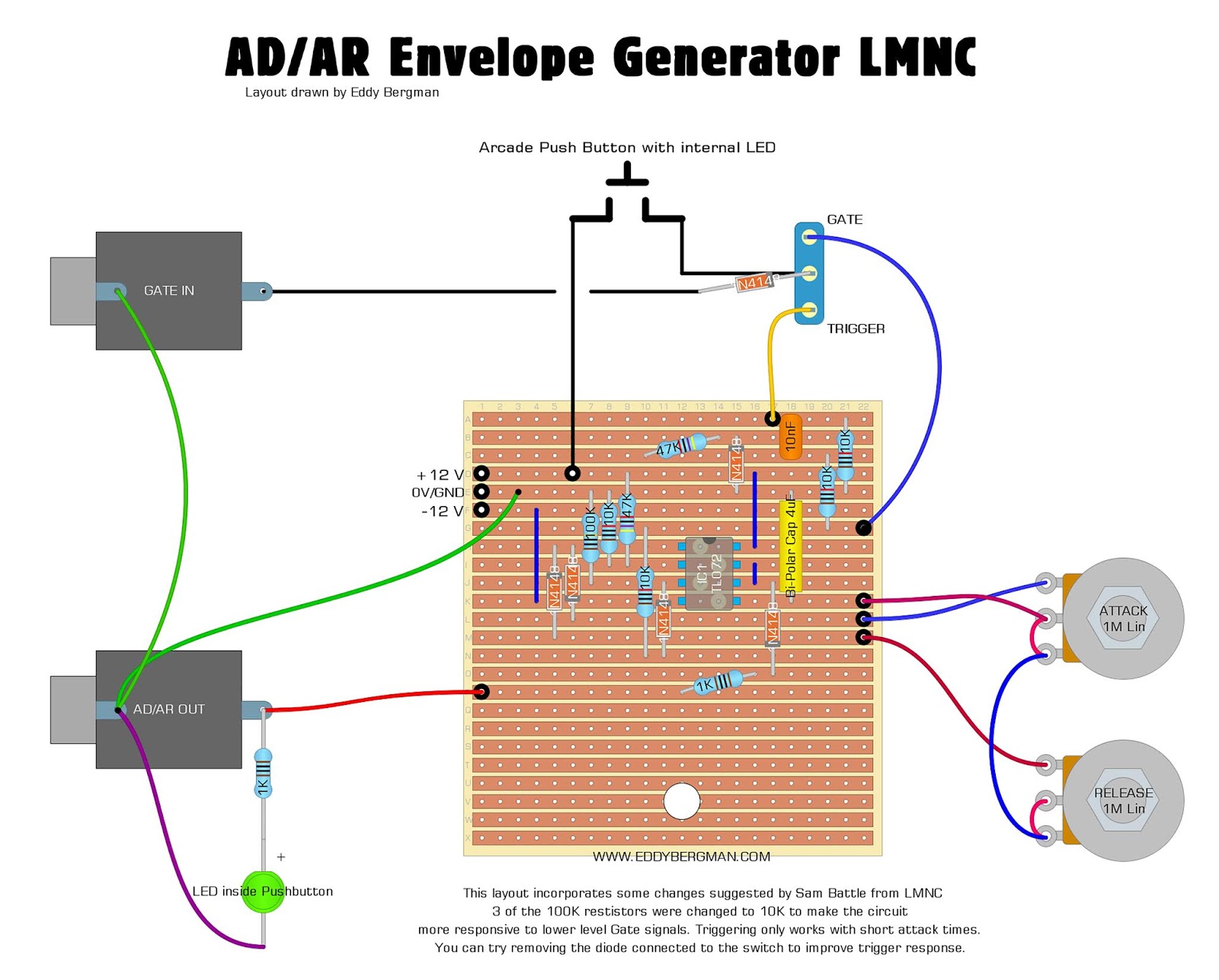
I’ve attempted to build a double AD/AR module, based on Eddy Bergman’s design, which is based on Sam’s Design (witch changes suggested by Sam himself).
Because my case isn’t very deep, and because I like the challenge, I make my own strip-board layouts. Unfortunately, only the right side is working, as in: no signal coming out of the left output and the LED indicator stays dark. I don’t really have trouble-shooting skills yet (and I have a few more modules lying around that I can’t get working…).
Checked connections with the multi-meter, making sure all my trace cuts were indeed cut.
Checking for shorts, scraping away anything that looked suspicious.
Took out TL074 and checked voltages at pin 4 and 11. One is -13 and the other +11.6. Close enough, right?
Replaced TL047, same result.
Checked panel connections and ground. Seem fine. Might have missed something though.
Checked resistor values, all seem fine.
Tried to check the capacitors… Seems fine? I tried the amp meter, but wasn’t sure of what I was doing. It seemed to drain over time.
Checked voltages of op-amp, both idle and while receiving gate signal from Beatstep Pro.
This is where I discovered that pin 8, 9 and 10 (the side that does work) are at a pretty stable -12v when idle and go up to +10v when receiving a gate signal, but pin 5, 6 and 7 fluctuate between 5-8v idle and 8-10v when receiving a gate signal. So, this seems like the problem to me, but I’m not smart enough to figure out the cause.
A few notes:
The module is powered by a Mean Well RT-65B, connected to a power rail made out of strip-board and 4x2 male headers.
I couldn’t find a non-polarised capacitor big enough, so I put two polarised tantalum capacitors in series, with cathodes connected: --|(–)|–. I read that this is fine, and my right side is indeed working perfectly!
I think the LED of the non-working side might have been glowing very dimly.
I didn’t want to come in here and go “Thing no work, help pls” without trying to fix it with my unga bunga caveman brain first. I think I’m onto something with the op-amp voltages, but I’m not experienced enough to figure out why it’s happening.
I’ll check these tomorrow, when I get back to my ‘workshop’.
Just to make sure: shouldn’t I be checking the left side in stead of the right? The right side is working fine and I didn’t see any difference between 1, 2 and 3 with it’s working counterparts 14, 13 and 12.
One possible issue could be that I swapped the IC while there was still a shorting issue going on, perhaps damaging the second IC in the same way as the first one.
I’ll check all this tomorrow, thanks for the reply!
Okay, so here’s what the voltages of the pins are at when I turned my power supply on, after pressing the gate button on the panel and after letting go:
All pots are turned to the left, so no A/R time. Replacing the TL074 with a brand new one did not help.
Pin 5 drains ONLY when I measure it. Does the draining happen because it’s connected to ground through the voltage meter? Does this mean there’s a ground issue? Because I looked into it and can’t find it. Both in and out jacks are properly grounded, so is the LED. Could it be that one of the 10uF tantalum caps are broken? They’re oriented the same way as on the right side, I’ve quadruple-checked that. Is there a way to check that with a multimeter?
If in the AR position, then when the button is pressed the gate should be present on pins 3 and 12. Pin 12 looks right but pin 3 is showing only 0 V. If the switch on that side is in the AR position then something is wrong with that input. Check continuity from push button to switch to resistor to diode to pin 3. With power on and button pressed there should be +12 V at switch pins 1 and 2 (latter is your G1), G6, and F7, and about +10 V at F9.
Additionally, if there is -12 V at pin 1 and the R pot is all the way down, pin 5 ought to be about -10 V, so it seems like there must be something else wrong there, but focus on the input for now.
Was this brand new one of the same batch as the first 2 ones? I’m asking because I had a TL074 in a circuit which did not seem to want to work. There were all kinds of conflicting voltages. So I tried another one and another one (of the same batch of 10 I bought). No joy. Then I took an LM324 which has the same pinout and all of a sudden all voltages made sense and the circuit worked. It turned out that from the batch of TL074s I had all were problematic.
Ah, I made a mistake in my picture above: pin 3 is doing exactly what you described: 0v idle, +10 at gate. Both switches are set to AR. G1, G6, F7 and F9 are all at the right voltages.
Replaced with an op-amp from a different module that works 100% (one of the few), but that didn’t help.
Thanks for posting the schematic, that’s a lot easier to follow!
OK, good. But Is pin 1 still -12 V when pin 3 is +10 V? It should not be. You should verify that.
And if it is, pin 5 should not be 0 V. Pin 1 connects to a diode at E5, the other side of the diode at D7 if the RELEASE pot is all the way down should connect directly to pin 5. Then -12 V on pin 1 (and E5) and 0 V on pin 5 (and D7) doesn’t make sense. I’d check those connections.
Shit, I really messed up that pic, haha! Yeah, basically 1, 2 and 3 are behaving exactly like 14, 13 and 12. Will double-check my data before posting next time…
I will check the connections tomorrow. Is it possible to damage diodes with prolonged heat from my soldering iron? I struggled with shitty AliExpress tin that didn’t have any rosin in it, even though it should have.
I did some sleuthing last night and found four problems:
D4 wasn’t connected. The aforementioned mess with the AliExpress tin made it really hard to see. Fixed it.
When I unscrewed the two pots to check if there’s something wrong, the lead between the wipers came loose. Fixed that as well.
Then I discovered that the Release pot was broken, as I didn’t get any continuity from wiper to left leg, even through it was turned all the way down. I don’t have any 1M pots left, so I replaced it with a 500K for now. Now pin 5, 6 and 7 of the TL074 are behaving correctly! Yay!
New problem: the output voltage to the OUT jack is too low, around 1.5v in stead of ~5v from the working side. Discovered that the 1K resistor at J2-J4 is broken (infinite ohm), so I replaced that.
Surely that’s the end, right? Nope, output still too low. Will continue later this week.
I’m a little annoyed that it’s problem after problem, but I am learning a lot! Thanks for helping me out with this!

