Hi guys. I have just got my order of AS 3340 IC’s for the Hero. Now I put one in the waiting Hero and plugged it in and got nothing. At least there was no smoke. After reading a bit I changed R9 and R12 to 47k. I know it only mentions R9 in the Doc’s but on the boards it says they need to be matched. Damned if I do and damned if I don’t. Anywho tested again and nothing still. I then tested all the test points all voltages are good. The only other thing that is different with this module is the jacks are 3 legged instead of 5. I tested them both and they seem to have the hot pin and gnd in the same place. Not sure what is going on. All help appreciated.
Not sure what your reasoning was, but R9 and R12 are just input and feedback resistors on an inverter stage, and they could be pretty much any value within reason as long as they’re matched and it wouldn’t affect anything. The only place I see R9 mentioned in build.md or howitworks.md is in conjunction with R12 so I’m confused as to what you’re referring to.
Jacks that fit the footprint but have only 3 pins are very probably fine.
Just to verify, I presume you looked on all the waveform outputs and saw nothing on any of them?
Have you tried changing the RV6 (Center freq) trimmer to see if that does anything?
Have you used a scope or an audio probe to check whether there are any waveforms present on the 3340 output pins? (Pins 4, 8, 10.)
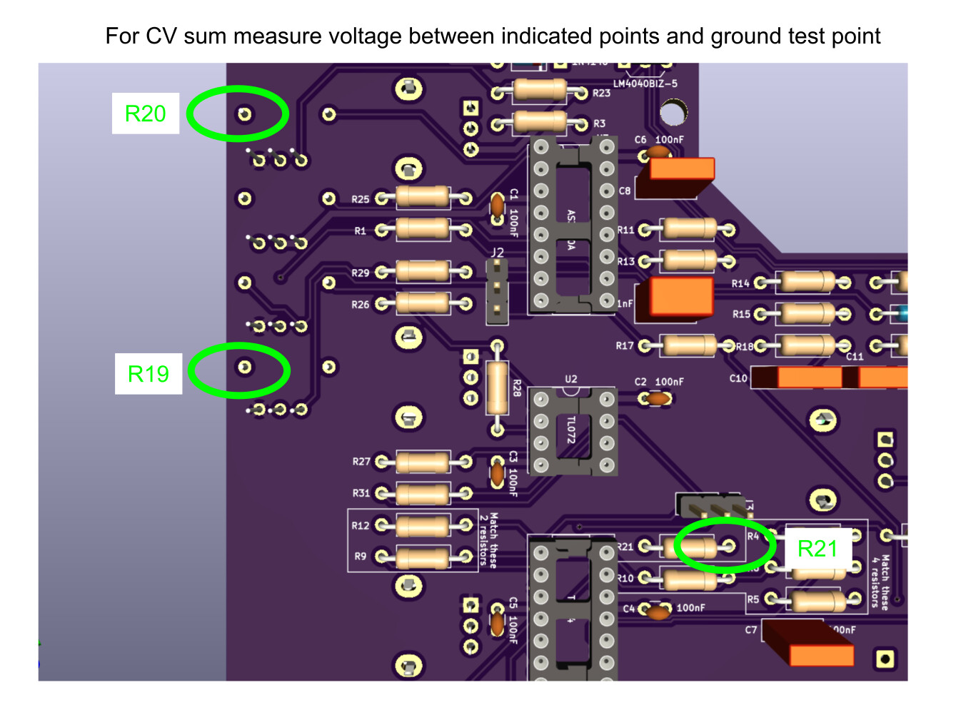
What’s the summed CV going into the 3340? It would be the sum of U1 pin 8, connected to R21, and the wipers of trimmers RV5 (Hi freq track) and RV6, connected to R19 and R20. You can measure at those resistors but you must measure on the sides of them that are not connected to the 3340 and each other:
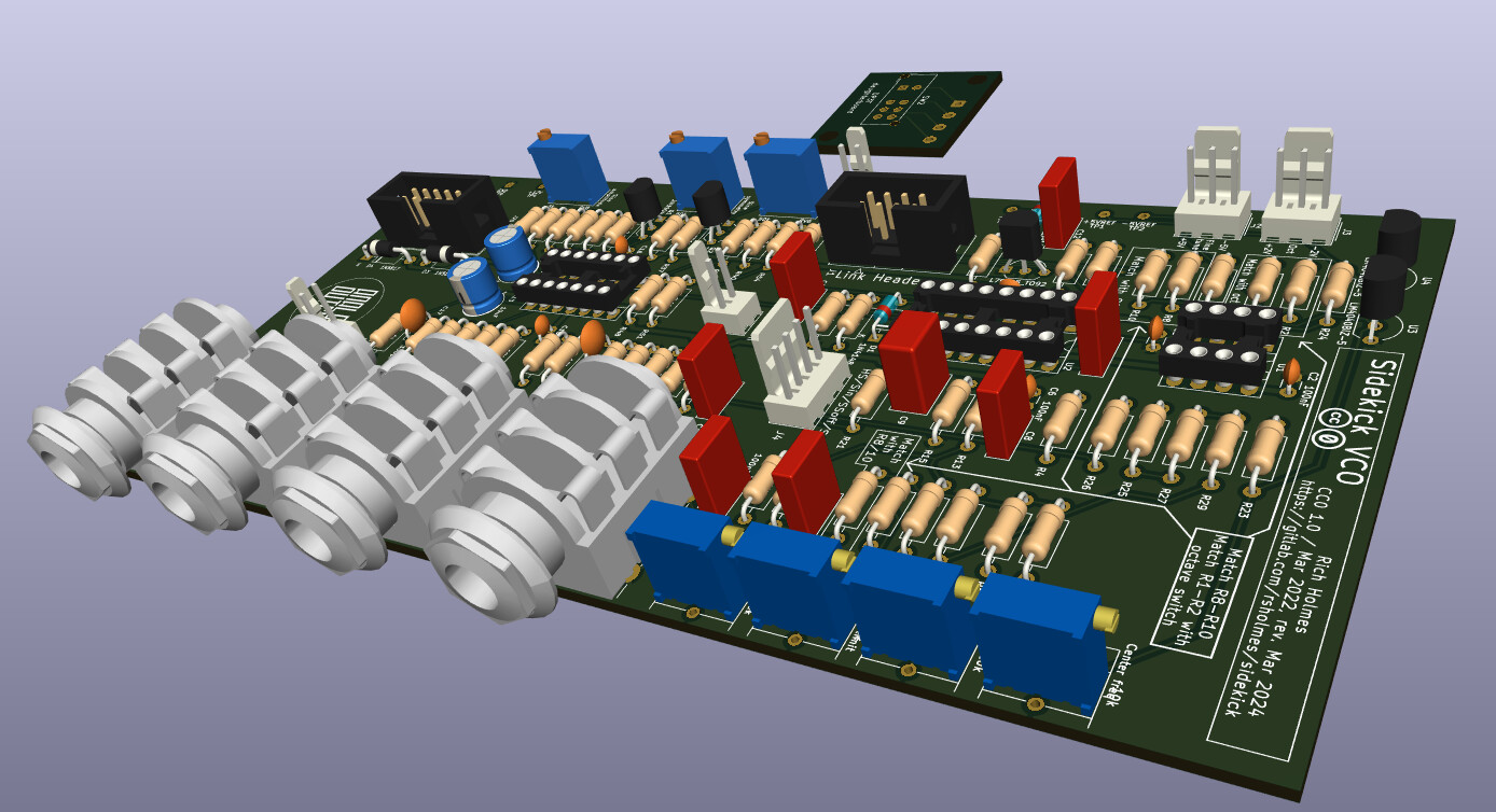
I decided to do a small revision to the Sidekick VCO. The RV1–4 trimmer footprints now can accommodate either a 3296P or a 3296W. The latter may be easier and cheaper to find, the downside being that you can’t adjust them via the front panel holes (and from behind, the 3296W screw may be awkward to get at past the panel pots).
yeah the bourns trim pots were kinda expensive . for my second batch of side kicks I used the 3296p trimmers found at AliExpress $ 1.50 U.S. for ten . they seem to be ok its not likely you will be changing the adjustments more than once our twice so they won’t get much wear.
tried to link to the page but it wouldn’t , it takes a bit of looking but they are there on the AilExpress site .
Thanks for the help Rich. I tested the resistances at all the points you suggested and they seem ok. The voltage at R19 is 2.8 and R20 is 5.5. The voltage on U1 pin 4 is 11.7v and pin 11 is -11.7v. I also changed the AS3340 for a CEM3340 out of a working Hero and the outcome is the same. I obviously have something wrong with a component somewhere. Getting frustrated so I am going to leave it alone for a while.
Anywhere a 3296W fits, you can put one of the others, like a 3296X. Same footprint, but the screw is on a different side. So still not adjustable on the frontpanel, but maybe less obstructed from the rear
X and W have the same footprint. Y and Z will fit in the P footprint. But W and Y are top adjust (maybe hard to reach with the panel pot nearby) while X and Z are side adjust on the narrow side — and unfortunately those would be blocking each other. It’s the wide side that would be most accessible and there isn’t a vertical trimmer (at least not from Bourns) with the screw on the wide side.
Hi there, currently building a hero VCO and had a question about some of the trimmer pots. The BOM gives 10k as values for RV2, RV5, and RV6, but lists Tayda A-586 for RV2 and Tayda A-592 for RV5-6. The latter of these is a 20k trimpot. The PCB footprints all say 10k. What’s correct here? (sidenote, the trimpots for the same controls on the sidekicks do not have this discrepancy, and are all 10k’s)
I borrowed a Cro from my radio club and tested outputs in various places. Output of the 3340 was ok. After testing here there and other places and also comparing with a working Hero, I was getting various results. At one stage I had the cro on the pins of the 6.5mm jack and had a signal. When I plugged a patch lead in no sound. I adjusted trimmers and had no luck. I am going to build another one and put the dodgy one aside.